KT24A/28A/30A/32A/36A/40A Repair Manual KT246A, KT28A, KT320A, KT32A, KT36A, KT40A General Pump is a member of the Interpump Group 8 Ref 300943 Rev.
GENERAL PUMP INDEX 1. 2. 3. 4. 5. 6. A member of the Interpump Group KT24A/28A/30A/32A/36A/40A SERIES INTRODUCTION . . . . . . . . . . . . . . . . . . . . . . . . . . . . . . . . . . . . . . . . . . . . . . . . . .Page 3 REPAIR INSTRUCTIONS . . . . . . . . . . . . . . . . . . . . . . . . . . . . . . . . . . . . . . . . . . .Page 2.1 Repairing Mechanical Parts . . . . . . . . . . . . . . . . . . . . . . . . . . . . . . . . . . . . . . .Page 2.1.1 Disassembly of Mechanical Parts . . . . . . . . . .
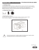
GENERAL PUMP A member of the Interpump Group 1. INTRODUCTION KT24A/28A/30A/32A/36A/40A SERIES This manual describes the instructions for repairing KT Series pumps, and must be carefully read and understood before performing any repair intervention on the pump. Proper pump operation and longevity depend on the correct use and maintenance. General Pump declines any responsibility for damage caused by the misuse or the non-observance of the instructions described in this manual. 2. REPAIR INSTRUCTIONS 2.
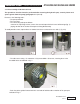
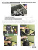
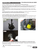
GENERAL PUMP A member of the Interpump Group 2.1.1 Disassembly of Mechanical Parts KT24A/28A/30A/32A/36A/40A SERIES The operations described must be performed after removing the hydraulic part, ceramic pistons and splash guards from the pump (paragraphs 2.2.3, 2.2.4). Remove in the following order: • The pump shaft tab • The rear cover • The connecting rod cap as follows: unscrew the cap fixing screws, remove the con-rod caps with their lower half-bearings (fig.
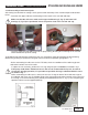
GENERAL PUMP A member of the Interpump Group KT24A/28A/30A/32A/36A/40A SERIES • Remove the pump shaft • Complete the disassembly of the con-rod units by removing them from the pump casing and removing the piston guide pins • Remove the pump shaft seal rings using common tools • Remove the piston guide seal rings as described below: Use the extractor, p/n F26019400 (1, fig. 5) and the gripper, p/n F27503800 (2, fig. 5).
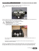
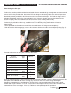
GENERAL PUMP A member of the Interpump Group 2.1.2 Reassembly of mechanical parts KT24A/28A/30A/32A/36A/40A SERIES After having checked that the casing is clean, proceed with assembly of the mechanical part as described below: • Assemble the upper and lower half-bearings in their seats in the con-rods and caps. Make sure that the reference marks on the upper half-bearing (1, fig. 6) and lower halfbearings (2, fig. 6/a) are positioned in their respective seats in the con-rod and cap.
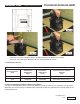
GENERAL PUMP A member of the Interpump Group KT24A/28A/30A/32A/36A/40A SERIES • Couple the con-rod caps to their shanks, referring to the numbering (1, fig. 9). Note the correct assembly direction of the caps. Fasten the caps to their respective con-rod shanks by means of M8x1x42 screws (fig. 10) lubricating both the underhead and the threaded shank, proceeding in two stages: 1. Manually turn the screws until they begin to tighten 2. Tightening torque: 22 Ft. Lbs. (30 Nm) Alternatively, ensure: 1.
GENERAL PUMP A member of the Interpump Group KT24A/28A/30A/32A/36A/40A SERIES • Mount the rear cover complete with the O-ring, positioning the dipstick hole upward. • Insert Oil in the casing as indicated in the use and maintenance manual. 2.1.3 Reduction Classes TABLE OF REDUCTIONS FOR CRANKSHAFTS AND CON-ROD HALF-BEARINGS Recovery Classes (mm) Part Number Half-bearing Upper Part Number Half-bearing Lower Correction on the Shaft Pin Diameter (mm) 0.50 F90922200 F90922500 Ø39.50 0/-0.02 Ra 0.
GENERAL PUMP A member of the Interpump Group KT24A/28A/30A/32A/36A/40A SERIES A) Disassembly/Reassembly of the crankshaft without bearings replacement After having removed the side covers as indicated in point 2.1.1, check the conditions of the rollers and their relative tracks. If all parts are in good condition, clean the components carefully with a degreaser and redistribute lubricant oil uniformly. The previous shims can be reused, taking care to insert them only under the indicator side cover.
GENERAL PUMP A member of the Interpump Group Determining the shim pack: KT24A/28A/30A/32A/36A/40A SERIES Perform the operation while the piston/con-rod guide units are assembled, the con-rod caps are disconnected and the con-rods are pushed downwards. Insert the crankshaft in the casing, checking that the PTO shank comes out from the provided side. Secure the PTO side flange to the casing, taking care with the lip seal as described previously and tighten the fixing screws to the recommended torque.
GENERAL PUMP A member of the Interpump Group KT24A/28A/30A/32A/36A/40A SERIES 2.2 REPAIRING HYDRAULIC PARTS 2.2.1 Dismantling the Head - Valve Units Operations are limited to inspection or replacement of valves, if necessary and, however, at the intervals indicated in the “Preventative Maintenance” table in chapter 11 of the use and maintenance manual. The valve units are assembled vertically inside the head.
GENERAL PUMP A member of the Interpump Group KT24A/28A/30A/32A/36A/40A SERIES Dismantling of the suction and outlet valve units can be carried out screwing in a sufficiently long M10 screw which can move the valve plate and remove the valve guide from the seat (1, fig. 20). If the threaded holes should not be present on the valve guides, dismantling can be easily carried out by leveraging with simple tools (fig 21). Ref 300943 Rev.
GENERAL PUMP A member of the Interpump Group KT24A/28A/30A/32A/36A/40A SERIES If the suction valve seats remain stuck on the head (for example scaling due to prolonged pump activity), operate as follows: Suction and outlet valves: For KT24A, 28A, 30A, 32A use tools #F26019400, and F27513700 (fig. 22) Suction valves: For KT36A and 40A use tools #F26019400, F27516900 (fig. 22) Outlet valves For KT36A and 40A use tools #F26019400 and F27513700 (fig 22) Ref 300943 Rev.
GENERAL PUMP A member of the Interpump Group 2.2.2 Reassembling the Head - Valve Units KT24A/28A/30A/32A/36A/40A SERIES Pay particular attention to the conditions of the various components and replace if necessary, and at the intervals indicated in the “Preventative Maintenance” table in chapter 11 of the use and maintenance manual. At every valve inspection, replace all O-rings and all anti-extrusion rings both in the valve groups and on the valve plugs.
GENERAL PUMP A member of the Interpump Group KT24A/28A/30A/32A/36A/40A SERIES To reassemble the various components, follow the reverse operations listed above as described in point 2.2.1. Reassemble the valve unit (fig. 24) to facilitate insertion of the valve guide in the seat, use a hammer, acting on the whole circumference (fig. 25). Insert the suction and outlet valve units, checking that they are down to end stroke in the head housing.
GENERAL PUMP A member of the Interpump Group KT24A/28A/30A/32A/36A/40A SERIES B) Separate the head from the pump casing. C) Extract the high pressure seals from the head and the low pressure ones from the support, using simple tools as indicated in fig. 27, being careful not to damage the respective housings. Pay attention to the order of seal pack disassembly as indicated in fig. 28 composed of: 1. 2. 3. 4. 5. 6. 7. Head ring HP seal Restop ring Seals support LP seal Seal ring O-ring Ref 300943 Rev.
GENERAL PUMP A member of the Interpump Group KT24A/28A/30A/32A/36A/40A SERIES 2.2.4 Dismantling the Piston Unit The piston unit does not require any routine maintenance. Maintenance is limited to visual checks only. To extract piston units: loosen the M7x1 piston fixing screws as indicated in fig. 29. Check and verify their conditions, replace if necessary At every disassembly all o-rings on the piston unit must be replaced. Ref 300943 Rev.
GENERAL PUMP A member of the Interpump Group 2.2.5 Reassembling the Head - Seals - Piston Unit KT24A/28A/30A/32A/36A/40A SERIES To reassemble the various components, follow the reverse operations listed above as described in pint 2.2.3, taking particular care: A) Seals pack Respect the same order used during disassembly operations. B) Lubricate components 2,3 and 5 with OCILIS silicone grease p/n F12001600; this operation is also deemed necessary to facilitate adjustment of the lip seal on the piston.
GENERAL PUMP A member of the Interpump Group 3. SCREW CALIBRATION KT24A/28A/30A/32A/36A/40A SERIES Screws are to be fastened exclusively using a torque wrench. Description Cover Fixing Screw Oil Discharge Plug Piston Fixing Screw Con-rod Fixing Screw Valve Cover Fixing Screw Outlet Valve Cover Fixing Screw Suction Head Fixing Screw 2nd PTO Flange Fixing Screw * Exploded View Position Fastening Fastening (From Owner’s Manual) Ft. Lbs. Nm 9 11 27 18 58 45 55 96 7.4 30 14.8 22.1* 132.8*** 88.
GENERAL PUMP A member of the Interpump Group KT24A/28A/30A/32A/36A/40A SERIES 4. REPLACING THE CON-ROD FOOT BUSHING During maintenance, if it becomes necessary to replace the con-rod foot bushing, proceed as follows: When removing the worn bushing, take great care not to damage or scratch the seat on the con-rod. Perform cold press fitting of the new bushing.
GENERAL PUMP 4. REPAIR TOOLS A member of the Interpump Group KT24A/28A/30A/32A/36A/40A SERIES Pump repairs can be facilitated by special tools. Part numbers are as follows: For Assembling Part: Seal bushing Ø 35; HP alternative seal ring Ø 24x35x6/4 Seal bushing Ø 45; HP alternative seal ring Ø 28x45x5.5/5 Seal bushing Ø 45; HP alternative seal ring Ø 30x45x7.5/4.5 Seal bushing Ø 44; HP alternative seal ring Ø 32x44x6/3 Seal bushing Ø 48; HP alternative seal ring Ø 36x48x6/3.
GENERAL PUMP A member of the Interpump Group 5. MAINTENANCE LOG KT24A/28A/30A/32A/36A/40A SERIES HOURS & DATE OIL CHANGE GREASE PACKING REPLACEMENT PLUNGER REPLACEMENT VALVE REPLACEMENT GP Companies, Inc. 1174 Northland Drive Mendota Heights, MN 55120 Phone:651.686.2199 Fax: 800.535.1745 www.generalpump.com email: sales@gpcompanies.com Ref 300943 Rev.