
User Guide


Gen-Eye USB, USBW, USBP
®
Video Pipe Inspection/Location System
7
Table 1—Reel Selection Guide
Reel Type Pipe Sizes
Lengths
Available
Standard
Reel
3” to 10”
(75 to 250mm)
200, 300, or 400 ft.
(60, 90 or 120m)
Mini Reel
2” to 3”
(50 to 75mm)
100 or 200 ft.
(30 or 60m)
CAMERA AND REELS
SELF-LEVELING COLOR CAMERA
The self-leveling color camera automatically keeps the picture right
side up as the camera glides though the line. You always have an
upright picture on the monitor, making it easier for you and your cus-
tomers to follow the action. Available on Standard size reels only.
COLOR CAMERA
Color camera provides a crisp, clear picture. Available on standard
and mini-reels.
CAMERA TRANSMITTER (512HZ)
The camera assembly includes a 512 Hz transmitter, located safely in
the spring behind the camera head. When the Command Module is
turned on, the transmitter is automatically activated.
NOTE: CARE SHOULD BE TAKEN WHEN GUIDING THE CAMERA
IN THE LINE AS EXCESSIVE BENDING AND TWISTING MORE
THAN 180 DEGREES MAY DAMAGE ELECTRONICS IN THE
SPRING.
SET UP
Pre-Inspection Procedure
1. Upon arrival to the job site, set up the Gen-Eye USB in an easily
viewable position where it will not interfere with the inspection.
2. Unwind the interface cord from the side of the reel and plug it into
the Reel Input Connector on the panel of the Command Module.
Insure the connector is properly aligned and then tighten.
3. Plug the AC cord into 120VAC input (or DC cord into 12VDC
input) on the Command Module panel, before plugging it into a
power source. Be sure the AC power source is properly
grounded.
DO NOT PLUG IN BOTH AC AND DC CORDS AT THE SAME
TIME!
4. Press the POWER button on the Keyboard to activate the Com-
mand Module. Press the POWER button on the monitor to acti-
vate the screen.
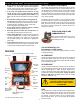
SKIDS
It is highly recommended that you use a skid at all times
to protect the camera head from abrasion in the pipe.
Skids lift the camera off the bottom of the pipe and center
it in the line for a better view and to allow the camera to
glide more easily though the line.
The standard reel comes with 2", 3", and 6" trap skids. Other optional
skids are available for 6", 8" and 10" lines:
To attach the skid, slide it over the front of the camera head, with the
lip of the skid at the front. Make sure the camera body is clean and
the set screws are tightened only until they touch the camera body.
Do not over tighten, as you may damage the camera housing.
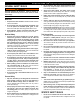
DOCKING ARM
The Docking Arm combines the reel and monitor into one portable
unit. It lets you adjust the height, axis, and angle of the Command
Module to suite each inspection location. Once the Docking Arm is
assembled, you can easily remove the Command Module to store the
unit indoors at night or protect it in the front of your truck. To assemble
the Docking Arm:
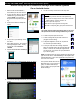
1. Place the Command Module upside down on a flat surface.
2. Line the pin in the block of the upper
Docking Arm with the guide hole in
the bottom of the Command Module
case, and tighten the knob to secure.
3. Swing the tube so it's 90 degrees
from the surface on the case and
tighten the knob.
4. Pick up the Command Module, flip it
over so the tube is below it, then slide
the tube into the lower Docking Arm
Assembly.
5. Tighten the knob on the lower Dock-
ing Arm to secure.
GL-SK GL-URS-1