
User Guide


Gen-Eye USB, USBW, USBP
®
Video Pipe Inspection/Location System
12
MAINTENANCE
CAMERA MAINTENANCE
CAMERA CLEANING
After every use, the camera should be cleaned and checked for possi-
ble damage that may have occurred during the inspection. External
scuffing of the camera housing is normal and should be of no con-
cern; however, use the trap skid to protect the camera and help it
slide around elbows more easily. The camera lens is made of sap-
phire and should be cleaned with a soft, damp cloth. Grease, dirt, or
scratches will affect the quality of the video picture.
DISCONNECT MACHINE FROM POWER SOURCE BE-
FORE PERFORMING MAINTENANCE ON MACHINE!
CAMERA FOCUS
All Gen-Eye cameras are pre-focused at the factory from approxi-
mately 3” to infinity and should not require any focus adjustments.
Should focus adjustments be required, please call the factory.
LIGHT HEAD REPLACEMENT
The lights for the Gen-Eye cameras use LED lighting and cannot be
replaced by the operator. These lights use very little power. Unless
physically damaged or extreme voltage is applied to them, they
should last indefinitely. If replacement is necessary, the camera
should be returned to the factory. The camera lights are wired in a
series/parallel configuration. This means that there are 4 sets of 4
(color camera) each wired together. Each set is wired in series and
then the 4 sets are wired in parallel. Therefore, should one lamp burn
out in one set, the other sets will still remain lit.
CAMERA REMOVAL
The camera and associated electronics are not user serviceable. Ser-
vicing must be done by qualified personnel. Contact the factory to
locate a service center near you. To use the Camera Test Terminal
(see instructions below) to diagnose a problem, or to return camera to
the factory, the following instructions should be used with extreme
care.
1. Disconnect the complete camera and spring assembly by remov-
ing the 3 screws (4-40 x ½ SSTL) that are countersunk into the
cone-shaped aluminum coupler at the end of the push cable.
The screws can be removed using the Xcelite allen wrench pro-
vided with the unit. Screws should be removed very carefully
and simultaneously. Each screw should be turned approximately
one (1) full turn alternatively, so as not to damage the connector.
While backing out each screw, hold the connector and camera
assembly together until all the screws are out and then unplug
the camera from the cable reel taking care not to lose the O-ring
or screws.
TO PREVENT DAMAGE TO THE CAMERA AND/OR
SYSTEM, DISCONNECT POWER FROM THE COM-
MAND MODULE BEFORE REMOVING OR RECON-
NECTING THE CAMERA TO THE REEL.
DO NOT FORCE THE CONNECTORS TOGETHER.
DAMAGE MAY OCCUR TO THE CONNECTORS.
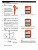
CAMERA TEST TERMINAL
Use this connector to troubleshoot video or light problems.
1. Disconnect the system from the power source.
2. Remove camera from cable assembly and plug into Camera Test
Terminal.
3. If the lights are still not working, chances are that one or more of
the lights will need replacement. Contact General for service.
This will help isolate where camera video or light problems may be
originating. Example: If the lights were not working when the camera
was connected through the cable reel, but they do work when you
plug directly to the front panel, this indicates a problem with the light
wire somewhere in the cable reel. (Always check fuses first.)
PUSH ROD AND REEL ASSEMBLY
CLEANING
The push rod and reel assembly should be kept clean from dirt. When
rewinding the cable back onto the reel after an inspection, it is good
practice to use a clean rag to wipe off any debris.
DO NOT USE A POWER WASHER TO CLEAN THE
REEL. WATER MAY GET INTO UNSEALED AREAS,
REEL HUB ASSEMBLY AND SLIP RING HOUSING,
CAUSING DAMAGE AND VOIDING THE
WARRANTY.
2. After disconnecting the camera assembly, inspect the O-ring for
any damage, and if worn, replace it with a new one. Also, when
replacing any O-rings, make sure there is no dirt or grit on it, as it
may not seal properly. Apply silicone grease or petroleum jelly to
the O-ring for proper sealing.
3. To reconnect the camera assembly, carefully align the rear con-
nector on the camera assembly and the push rod connector.
When aligned, push the connectors together and replace the
screws. (If the connectors do not align properly, turn the camera
body slowly while slightly pushing the two connectors together
until you feel them align properly together.)