
User guide

iv RD7000 Operation Manual
Section 7. – Using Accessories
23
7.1 About accessories 23
7.2 Receiver clamps 23
7.2.1 When to use clamps 23
7.2.2 Connecting a clamp 23
7.2.3 Available receiver clamps 24
7.3 Transmitter clamps 24
7.3.1 Connecting the clamp 24
7.3.2 Available transmitter clamps 25
7.4 Sondes 25
7.4.1 When to use a sonde 25
7.4.2 Choosing a suitable sonde 25
7.4.3 Preparation 25
7.4.4 Propelling a sonde 25
7.4.5 Locating and tracing a sonde 26
7.4.6 Checking sonde depth 26
7.4.7 Types and range of sondes 27
7.5 Stethoscopes 28
7.5.1 When to use a stethoscope 28
7.5.2 How to use a stethoscope 28
7.5.3 Types of stethoscope 28
7.6 Submersible antenna 28
7.6.1 When to use a submersible antenna 28
7.6.2 How to use a submersible antenna 28
Section 8. – Fault-Finding
30
8.1 About fault-nding 30
8.2 Preparation 30
8.2.1 Connecting the transmitter 30
8.2.2 Reference readings 30
8.3 How to nd a fault 31
Section 9. – Appendices
32
9.1 Care and maintenance 32
9.1.1 General 32
9.1.2 Batteries and power supply 32
9.1.3 Cleaning 32
9.1.4 Disassembly 32
9.1.5 Service and maintenance 32
9.2 Upgrading rmware 32
9.3 eCAL™ 32
9.4 Specications for the receiver and
transmitter
33
9.5 Supported frequencies 33
9.6 Supported accessories 34
Table of figures
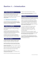
Figure 2.1: RD7000 receiver 2
Figure 2.2: receiver keypad 2
Figure 2.3: receiver LCD 2
Figure 2.4 RD7000 transmitter 4
Figure 2.5: Rechargeable battery pack 4
Figure 2.6: transmitter keypad 4
Figure 2.7 transmitter LCD 4
Figure 4.1 Line tracing 13
Figure 4.2: Pinpointing a target line 13
Figure 4.3: Pinpointing with Peak/Null 13
Figure 5.1: Taking a depth reading 16
Figure 5.2: Depth readings 16
Figure 5.3: Current readings 18
Figures 5.4 – 5.6: Taking current readings 18
Figure 8.7: Current readings using transmitter
signals
19
Figures 6.1 – 6.4: Interference from services 20
Figure 6.5: Making double-ended connections 22
Figure 7.1: Connecting a receiver clamp 23
Figure 7.2: Standard clamp 24
Figures 7.3 – 7.4: Connecting transmitter clamps 24
Figure 7.6: Sonde deployment 26
Figure 7.7: Locating a sonde 26
Figure 7.8: Calculating sonde depth 26
Figure 7.9: Standard sonde 27
Figure 7.10: Super small sondes 27
Figure 7.11: Sewer sonde 27
Figure 7.12: FlexiTrace 27
Figure 7.13: Using a submersible antenna 29
Figure 8.1: Cable sheath fault-nding 31
Figure 8.2: Locating cable sheath faults with the
receiver and A-frame
31