RD7000 Radiodetection’s general utility cable and pipe locator.
Preface Before you begin Thank you for your interest in Radiodetection’s RD7000 cable and pipe locator. or one above another. Exercise caution and due diligence when conducting any survey. Making a direct connection to live power lines is extremely dangerous to life. Do not attempt any direct connection unless you are fully trained and qualified to do so. The RD7000 delivers the very latest in cable and pipe location technology in a powerful yet ergonomic and lightweight design.
Training Radiodetection provides training services for most Radiodetection products. Our qualified instructors will train equipment operators or other personnel at your preferred location or at Radiodetection headquarters. For more information go to www.radiodetection.com or contact your local Radiodetection representative. Trademarks RD7000, RD8000, RD4000, eCAL, Centros, TruDepth, SideStep, SideStepauto and StrikeAlert are trademarks of Radiodetection Ltd.
Table of contents Preface i Before you begin i 3.8.1 Using SideStepauto Important notices i 3.9 Dynamic overload protection 9 3.8 SideStepauto™ 9 9 10 3.10 StrikeAlert™ General i Safety i Batteries i 3.11 Antenna modes 10 FCC and Industry Canada statements i 3.12 Backlight 10 Training ii 3.13 Audio 10 Trademarks ii 3.14 Transmitter power output 11 10 3.10.1 Using StrikeAlert Copyright statement ii 3.14.1 Adjusting power output Section 1. – Introduction 1 3.14.
Table of figures Section 7. – Using Accessories 23 7.1 About accessories 23 Figure 2.1: RD7000 receiver 2 7.2 Receiver clamps 23 Figure 2.2: receiver keypad 2 7.2.1 When to use clamps 23 Figure 2.3: receiver LCD 2 7.2.2 Connecting a clamp 23 Figure 2.4 RD7000 transmitter 4 7.2.3 Available receiver clamps 24 Figure 2.5: Rechargeable battery pack 4 24 Figure 2.6: transmitter keypad 4 7.3.1 Connecting the clamp 24 Figure 2.7 transmitter LCD 4 7.3.
Section 1. – Introduction 1.1 About this manual This manual provides cable and pipe survey professionals with comprehensive operating instructions for the RD7000 receiver and transmitter system. Before operating the RD7000 system it is very important that you read this manual, noting all safety warnings and procedures. 1.1.1 Additional documentation This manual introduces the Centros Manager software suite but provides only limited installation and operating instructions.
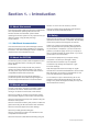
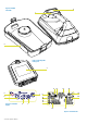
2 1 3 4 5 6 Figure 2.1: RD7000 receiver 16 9 13 11 12 13 7 8 14 15 9 10 17 18 24 25 Figure 2.2: receiver keypad 19 20 21 22 23 Figure 2.
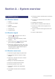
Section 2. – System overview 2.1 RD7000 receiver 2.1.1 Receiver features 1. Keypad. 2. LCD with auto backlight. 3. Speaker. 4. Battery compartment. 5. Accessory slot. 19. Accessory indicator: Indicates when an accessory is connected. 20. A-Frame icon: Indicates when the A-Frame is connected. 21. Operating mode indicator. 22. Null / Peak icon: Indicates antenna selection. 23. Sonde icon: Indicates that the signal source is from a sonde. 24. Line icon: Indicates that the signal source is from a line. 6.
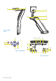
Figure 2.4 RD7000 transmitter 2 1 3 Figure 2.5: Rechargeable battery pack 4 11 5 7 6 12 13 18 19 9 20 14 15 16 Figure 2.6: transmitter keypad 8 7 17 10 21 Figure 2.
2.2 Tx1, Tx3 and Tx10 transmitters 2.2.1 Transmitter features 1. Keypad. 2. LCD. 3. Removable accessory tray. 4. Rechargeable battery pack. 2.2.2 Transmitter keypad 5. Power key : Switches the unit on and off. Opens the transmitter menu. 6. Frequency key navigation key. : Selects frequency. Menu 7. Up and down arrows : Adjusts the output signal. Scrolls through the menu options. 8. Measure key : Toggles measurement display between volts, current and impedance.
Section 3. – Basic Operation 3.1 Starting the system The receiver and transmitter are battery powered. Install good quality D-cell NiMH or Alkaline batteries into the receiver and transmitter battery compartments. Alternatively, you can power the transmitter from a mains or vehicle power source using a Radiodetection supplied adapter. To switch the receiver or the transmitter on, press and hold the keypad Power Key for two seconds. When you switch the system on it will perform an LCD segment check.
5. Press the key to accept your selection and return to the main menu. 6. Press the screen. key to return to the main operation 3.2.2 Language The receiver and transmitter support a number of languages. You can specify your preferred language using the menu system. To select your preferred menu language: 1. Press the key momentarily to enter the menu. 2. Scroll to the LANG option using the arrow keys. 3. Press the antenna key ( on the transmitter) to enter the LANG submenu. 4.
• FREQ: Enable or disable individual frequencies. • ALERT: Enable or disables StrikeAlert™. • BATT: Sets battery type. NiMH or ALK. • ANT: Enable of disable any antenna mode with the exception of Peak. 3.3.4 Navigating the transmitter menu 1. First power up the transmitter. 2. Press the key to enter the menu. 3. Use the or menu options. 4. Press the arrows to scroll through the key to enter the option’s submenu. 5. Press the key to return to the previous level or exit the menu. 6. Press the screen.
3.8 SideStepauto™ 3.6.3 Selecting frequencies It is important to select the correct or appropriate frequency for your particular application. For more information see Section 6 or refer to the ABC & XYZ of locating buried pipes and cables, which is available as a free download from www.radiodetection.com To select a frequency on the receiver: 1. Switch the unit on by pressing the if you have not already done so. key, 2. Press the key to cycle through available frequencies. 3.
3.10 StrikeAlert™ 3.12 Backlight StrikeAlert detects shallow power cables and warns the operator with an audible alarm. The alarm is characterized by a rapid warbling sound. StrikeAlert is enabled by default; you can enable and disable StrikeAlert using the procedure detailed below. NOTE: StrikeAlert will not sound when the receiver’s volume is muted. To disable StrikeAlert key to enter the menu. 3. Scroll to the ALERT option using the arrows. 4. Press the or key to enter the ALERT menu. 5.
3.14 Transmitter power output The transmitter supports several power output modes to help you select the optimal settings for your requirements whilst helping to prolong battery life. 3.14.1 Adjusting power output To adjust the power output: 1. Switch on the transmitter. 2. Press the or power output. keys to increase or decrease 3.14.2 Boost (Tx3 and Tx10 only) Boost allows the transmitter to output its maximum wattage for a specified period of time in minutes.
Section 4. – Locating cables and pipes This section introduces the principals and techniques of locating buried cable and pipe utilities with the RD7000 system. For more information on the theory of cable and pipe location, please refer to ABC & XYZ of locating buried pipes and cables, which is available from www.radiodetection.com Null mode is used to verify a locate signal in environments with limited or no electromagnetic distortion.
4.3 Pinpoint To select Peak/Null mode: 1. Press and release the receiver on. key to switch the 2. Press the antenna key until the Peak/Null mode icon is displayed on the LCD. 4.2 Trace Line tracing can be accelerated by switching the receiver to null response. Pinpointing a target line in peak mode, defines the exact position of a target line after it has been traced and its position is approximately known.
Switch to null response mode and move the receiver to find the null position. If the position of the peak and the null pinpoints correspond, it can be assumed that the pinpoint is precise. The pinpoint is not precise if the marks do not correspond, but both marks will show an error to the same side. True line position will be close to peak position. The line lies half the distance to the other side of the peak position as the distance between the peak and the null positions. 4.
The first person operates the transmitter and the second person operates the receiver. The transmitter induces a signal onto lines as it passes over them and the lines are then detected with the receiver 20 paces upstream or downstream of the transmitter. Hold the transmitter with its length aligned with the assumed direction of any lines. The second person holds the receiver at the start of the area to be searched and with the receiver antennae at right angles to the probable direction of the buried lines.
Section 5. – Depth and current readings 5.1 Depth readings The RD7000 can measure the depth of buried conductors down to depths of approximately 6 meters (20 feet). The depth measurement is to the center of the pipe or cable. The best readings are detected from signals outputted by a transmitter rather than from passive sources. The RD7000 is capable of determining depth when locating passive power signals.
5.2 Verifying depth measurements Check a suspect or critical depth reading by lifting the receiver 50mm (2 inches) above the ground and repeating the measurement. If the measured depth increases by the same amount it is a good indication that the depth reading is correct. Depth measurements should be accurate to ±2.5% if conditions are suitable.
5.3 Current readings Figures 5.4 – 5.6: Taking current readings 5.3.1 Identification using current measurements mA mA Measuring current value on a line helps confirm the identity of the line and provides information about the condition of cable insulation or pipe coating. 5.3.2 About current measurements The transmitter applies a signal or current onto a target line. The current decreases in strength as the distance from the transmitter increases.
5.3.3 Applying a transmitter signal mA mA mA The transmitter signal can be connected, clamped or induced to the target line in the same way as the signal for line tracing is applied. 5.3.4 Signal current measurements Pinpoint the line and confirm the accuracy of the peak pinpoint with a null pinpoint. Check the receiver is directly over the line, with the antennae at right angles to it and vertical. The receiver will automatically estimation and display the depth reading on the LCD.
Section 6. – General Locating tips 6.1 Eliminating services 6.1.1 Induction If several conductors are running parallel and it is not possible to connect a transmitter, each line may be located separately. Proceed as follows: 1. Perform a sweep of the area to find the position and number of conductors in the area. 2. Map the direction in which the conductors are going. To trace the lines: 1. Select induction mode on the transmitter. 2. Select the same frequency as on the receiver. 3.
• Identify points where lines may be bonded or in close proximity to each other. Work toward these points rather than away from them. For example, if gas and water pipes are bonded within a building, apply the signal at the valves or access points in the road rather than in the building. • Reduce coupling to a parallel line by using a low signal frequency where available. • Return signal flowing on another line. Use a doubleended connection to by-pass the ground return if possible.
6.3 Double-ended connections Large diameter water pipes and gas distribution pipes that are laid in sections sometimes have insulated joints between the sections and can be difficult to locate using a single ended connect. This is because when using a single ended connection ground return, signals can often cause confusion by returning to the transmitter along other lines.
Section 7. – Using Accessories 7.1 About accessories Both the transmitter and receiver are compatible with a wide range of accessories, including most RD4000 accessories. Use clamps to help apply a signal to pipeline or live wire. Use an A-Frame to provide the RD7000 receiver with advanced fault-finding capabilities. When an accessory is connected, the receiver or transmitter will instantly recognize it and will enable the mode appropriate to the accessory.
7.2.3 Available receiver clamps 7.3.1 Connecting the clamp Plug the clamp into the transmitter output socket. Standard clamp The clamp plugs into the receiver accessory socket and is used for cable identification at points where the cable can be accessed. The standard clamp is suitable for cables up to 100mm (4 inches) diameter. Put the clamp around the pipe or cable and ensure that the jaws are closed. Switch the transmitter on.
7.3.2 Available transmitter clamps Although transmitter and receiver clamps look the same, they have different internal windings. To prevent the wrong clamp being connected, transmitters and receiver clamps have plugs of a different orientation. Standard signal clamp The standard clamp applies the transmitter signal very selectively and effectively to a target cable up to 100mm diameter at 8/33kHz frequency or up to 75mm diameter cable at 512Hz.
7.4.5 Locating and tracing a sonde Insert the sonde in the drain or duct access and locate it while it is still just in view at the drain or duct entrance. Hold the receiver vertical directly over the sonde with the antenna in line with the sonde. Adjust the receiver sensitivity so the bar graph reads between 60% and 80%. The sonde radiates a peak field from the center of its axis with a ghost signal at each end of the peak.
7.4.7 Types and range of sondes Ø 39mm Standard sonde The standard sonde combines compact size with a strong signal and is the standard sonde for most applications unless a smaller size, greater depth or rugged construction sonde is required. 105mm Figure 7.9: Standard sonde Super small sonde This is a specialized sonde particularly suitable for no-dig applications. This type of sonde has an interchangeable battery compartment so that the length of the sonde can be altered.
7.5 Stethoscopes 7.5.1 When to use a stethoscope At times, it may not be possible to put a clamp around a cable because of congestion or because of inaccessibility. A stethoscope antenna should be used in the place of the clamp to identify cables. 7.5.2 How to use a stethoscope Plug the stethoscope into the receiver accessory socket. Press the concave head against each cable in turn to detect a maximum signal. 7.5.
Tips for using a submersible antenna The user in the boat should be a specialist or have considerable experience using a receiver so that they can give concise instructions to the diver. It is prudent for the pair to practice working together on dry land before attempting to locate underwater. Using the antenna the diver should locate and trace a known line blindfolded receiving directions from the user with the receiver out of sight of the line and the diver.
Section 8. – Fault-Finding 8.1 About fault-finding The RD7000TL and PL are capable of locating cable to ground faults caused by damaged cable sheaths. This process is known as 8K Fault-Finding as it uses an 8kHz signal applied to a target line with a transmitter. The accessory A-frame is used to locate cable sheath faults on power and telecom cables. To use Fault-Find you will need the following equipment: • RD7000TL or PL receiver • Tx3 or Tx10 transmitter • Accessory A-frame connection leads. 8.
Take the dB reading and keep it for reference. If there is a single fault on the cable, it will be approximately the same dB value as the reference reading. NOTE. To establish how often to take readings on the cable, move away from the ground stake and take further readings until the arrow has difficulty in locking and the dB reading is low. Measure the distance that the receiver is now away from the ground stake.
Section 9. – Appendices 9.1 Care and maintenance The RD7000 receiver and transmitter is robust, durable and weatherproof. However you can extend your equipment’s life by following these care and maintenance guidelines. 9.1.1 General Store the equipment in a clean and dry environment. Regularly validate your equipment using eCAL. Validation ensures the equipment is valid according to its original factory calibration. (See Appendix 13.
9.4 Specifications for the receiver and transmitter Sensitivity 6E-15Tesla, 5µA at 1 meter (33kHz) Dynamic range 140dB rms /√Hz Selectivity 120dB/Hz Depth accuracy Line: ± 2.5% tolerance 0.1m (4”) to 3m (10ft) Sonde: ± 2.5% tolerance 0.
9.6 Supported accessories Description Part Number Transmitter Accessories UK Plug Connector 10/AC1231-4KTX-LPC-UK Euro Plug Connector 10/AC1231-4KTX-LPC-EUR Live Cable Connector 10/AC1231-4KTX-LCC 2” (50mm) Transmitter Clamp 10/TC2136-4KTX 4” (100mm) Transmitter Clamp 10/TC1769-4KTX Earth Reel 09/310-4KTX Mains power AC transformer to 12V DC New 10/RD7K8KUMPSU Tx Direct Connection Lead 17/TX2609E1 Earth Stake 04/PT1505N27 New Short Earth Stake 04/ET2980P8 8.
512Hz Sonde 10/SCO412-512 Spring Coupling M10 Male 10/SU0335 Flexrod Coupler (Joins two Flexrods together) 02/FR0818N1 Flexrod Blank for Machinery 02/FR0336 115mm (4.5”) Diameter Floats/Pair 10/SU0344 M10 Thread Protecting Nipple 02/P105O External Shell for heavy-duty applications (Diameter as Sewer Sonde) 10/SC0963 Plastic or Cane Rod Connector, Male 02/SU0339 GD Rod Connector.
World leaders Radiodetection is a proud member of the SPX group of companies, which provide technical products and service solutions worldwide. Radiodetection and its associated companies specialize in the design and manufacture of products for the location and maintenance of underground pipes and cables. Our aim is to be viewed as the supplier of choice of ‘high performance’ quality equipment using advanced product technologies. We are also committed to both design innovation and customer support.