ADAMS MODEL CD-22 MODEL CD-28 CONTINUOUS DUTY WINCH Installation, Operation and Maintenance Manual General Machine Products Co., Inc. 3111 Old Lincoln Highway Trevose, PA 19053 USA Tel: +1.215.357.5500 Fax: +1.215.357.6216 Email: info@GMPtools.
TABLE OF CONTENTS BASIC DETAILS …………………………………………………………... Page 2 GENERAL ………………………………………………………………….. Page 2 MAJOR COMPONENTS …………………………………………………... Page 3 ACCESSORIES …………………………………………………………….. Page 3 USE …………………………………………………………………………. Page 3 HYDRAULIC REQUIREMENT …………………………………………... Page 3 INSTALLATION …………………………………………………………... Page 3 CONTROLS ………………………………………………………………... Page 4 WINCH CLUTCH AND DRAG BRAKE INFORMATION .……………... Page 4 CALIPER BRAKE ASSEMBLY INSTALLATION ……………………….
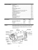
MAJOR COMPONENTS • • • • • • • • ACCESSORIES Levelwind Model CH-22 or CH-28, Overwind or Underwind (Derived from Bell System Spec. 8414). Three speed transmission-hydromechanical Model 240-584 (Derived from Bell System Spec. 8111). Three speed transmission-hydraulic Model 230-1600 Drum shaft extension USE The Models CD-22 and CD-28 can be driven mechanically, hydromechanically or hydraulically.
Sufficient clearance should be allowed between the front body panel or other restrictive members and the winch to permit normal maintenance. For standard installations, place the winch assembly on the chassis frame so that the levelwind is facing rearward and the drum shaft is projecting toward the right or curb side. The normal direction of drum rotation for pulling in is clockwise when viewed from the right side of the vehicle. The wire rope is wound onto the drum from the top.
DISC TYPE DRAG BRAKE On units manufactured before February 15, 1980, there are three control positions for the winch clutch and disc type drag brake. Using the mechanical pushpull shift, with the control lever installed at the rear of the vehicle, operation is as follows: Control handle all the way in - clutch engaged for pulling. Control handle partially out - clutch disengaged for free spool operation. Control handle all the way out and holding - applies drag brake to drum.
The primary brake assembly P/N 17134 will be mounted at the factory on the left side, top surface of the forward winch frame rail using mounting bracket -P/N 15277 with four bolts, nuts and lockwashers. The brake disc P/N 24117 will be mounted at the factory on the outboard surface of the left side drum flange using eight machine screws.
IMPORTANT NOTE: WHEN THE WIRE ROPE IS BEING PAYED-OUT UNDER POWER, THE WINCH IS BEING DRIVEN AGAINST THE BRAKE. CONSEQUENTLY, EXCESSIVE HEAT WILL DEVELOP IN THE AUTOMATIC BRAKE HOUSING, POSSIBLY CAUSING THE OIL TO BOIL OVER. If it is necessary to pay the wire rope out under power, do not operate in this manner for more than one hundred feet. Drive the winch at slow speed only. To pay-out wire rope over one hundred feet in length, the winch drum should be placed in the free spool position.
To control the drum speed in free spool: For winches with a disc type drag brake, pull the single clutch control lever all the way out and hold according to the amount of braking required. For winches with a band or caliper type drag brake, actuate the separate control lever and hold according to the amount of braking required.
The oil level plug should always be removed before adding oil to avoid over-filling. The automatic brake housing should be checked after seventy-five hours of operation. It should be completely drained and filled with new transmission oil at least once each year. Drive and Final Drive Housing The oil level in these two housings will be the same because of the flow-through lubrication design. To check for the proper oil level, remove the oil level plug on the front side of the final drive housing.
Make certain that the wire rope is properly attached to the drum and that no less than one half of the first lay remains on the drum at all times. Make certain that the eye at the end of the winch line is properly spliced or swaged. Wire rope (winch line) may be old, damaged or weakened by such defects as kinks, cuts, extreme bends or loops. Such conditions are potentially dangerous and detrimental to safe operation of the winch.
Reverse bending of the wire rope should always be avoided or kept to a minimum. Wire rope should always be under tension when spooling onto the winch drum. When the winch drum is in free spool and the drum shaft extension only is being used with a capstan or reel, the wire rope pulling end should be affixed to the drum. This will prevent the rope from unwinding or clock-springing. Drum rotation can be controlled with the drag brake applied.
SPECIFICATIONS Line pull & line speed capacities Hydraulic Tri-Drive Three-Speed Transmission (Model 230-1600) Winch Input Control Valve Maximum Rated Line Pull (lbs.) Gear Ratio Position 19.9:1 19.9:1 19.9:1 High Intermediate Low Winch Line Speed (ft./min.) 30 GPM Bare drum Full Drum Bare Drum Full Drum 10,000 4,500 82 177 16,100 7500 49 106 12,000 27 58 1 Winch Gear Ratio 19.9:1 Maximum Rated Winch Line Speed* Line pull (Ibs.) (Ft./min.