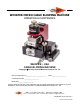
WHISPER MICRO CABLE BLOWING MACHINE OPERATION & MAINTENANCE WHISPER – USA CABLE BLOWING MACHINE Copyright 2013 by General Machine Products Co., Inc QC Final Inspection by:_________________________ Date:__________________ Unit Serial Number:__________________ Build Date:__________________ All rights reserved. No part of this publication may be copied, reproduced or transmitted in any form whatsoever without the written permission of General Machine Products Co., Inc.
REVISION HISTORY Rel.no 01 Date 09/13 Details Original issue Author A KONSCHAK Page 2 General Machine Products Co., Inc.
CONTENTS 1. Safety Instructions 2. Critical Points 3. General Description 4. Specification 5. Operating procedures 6. Maintenance 7. Monthly Service – check list 8. Service History Record 9. Tube integrity and Lubrication 10. Recommended Spares List APPENDICES Appendix 1 Appendix 2 Appendix 3 Cable and tube insert selection chart. Recommended torque control potentiometer settings Counter/Ratemeter Programming Instructions GMP Limited Warranty Page 3 General Machine Products Co., Inc.
1. SAFETY INSTRUCTIONS This Equipment should be used only by personnel who have been given the appropriate training and who are competent to use it. These instructions are to be made available to operators of this equipment at all times. Failure to observe these safety instructions could result in serious personal injury and/ or property damage. WORK AREA AND GENERAL SAFETY 1. Read and understand the operation and maintenance manual supplied with this equipment.
16. No personnel are to be in manholes or ducts when the Cable Blowing Machine is being operated. 17. The machine must be operated on firm ground. 18. Stay clear of cables or lines under tension. 19. Stay clear of pressurized air line and tube. 20. Only use the machine for its intended purpose. Do not use the roller drive without the air chamber to push or to retrieve cable or blow air in the far end of tube to help cable recovery. 21. Do not place cable drum too close to the Cable Blowing Machine. 22.
GENERAL PNEUMATIC SAFETY INSTRUCTIONS The GMP Whisper Micro Cable Blowing Machine is a pneumatic device, using pressurized air to project cable at high velocities. Please observe the following precautions when operating the Cable Blowing Machine: 1. Compressed air can cause flying debris. This could cause personal injury. Always wear personal protective equipment. 2. Ensure no personnel are in the manhole at the far end of the cable run. Severe personal injury may result. 3.
2. Critical points that dramatically affect the operation of the cable blowing machine. Pressure on the cable should be set as per the instructions. Rollers to be closed at all times when cable is installed into machine. Cord seals in air chamber correctly fitted to provide good sealing. Correct cable seal fitted. Tube fully connected and pressure-tested. Tube connecting fittings are suitable for operating at 220 PSI air pressure. Tube clamp securely tightened.
DISCLAIMER General Machine Products Co., Inc takes care in the design of its products to insure that the cable is protected during installation. Due to the variety and different methods of cable manufacture the responsibility of checking the cable compatibility with the equipment lies with the user. Therefore, GMP can not accept liability for any damage to the cable. Page 8 General Machine Products Co., Inc.
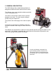
3. GENERAL DESCRIPTION The GMP Whisper Micro Cable Blowing Machine is designed to install micro fiber cable into micro tubes. The Whisper uses a user supplied variable speed drill to drive a compliant roller. The shaft is covered with a rubber roller to prevent damage to the cable. The roller may be changed quickly using one simple tool. The pressure the rollers apply to the cable is adjustable. A full range of accessories is available to allow the machine to handle a wide range of cables and micro tubes.
4. SPECIFICATIONS Cable size: 0.08” to 0.335” 2.0 to 8.5 mm Tube size: (OD) 0.158” to 0.709” 4 to 18 mm Cable speed: 0-300 ft/min 0-90 m/min Maximum air pressure: 220 psi. 15 bar. Power requirements: Variable Speed Drill (not included) with adjustable torque Weight 12 lbs. approx. 5.4Kgs approx. Dimensions (ht x length x width) 8.5” x 9.7” x 8.1” 216mm x 246mm x 206mm Page 10 General Machine Products Co., Inc.
5. OPERATING PROCEDURE IT IS IMPERATIVE THAT ALL PERSONS USING, OPERATING OR MAINTAINING THIS CABLE BLOWING MACHINE: ● HAVE RECEIVED COMPREHENSIVE TRAINING IN THE USE OF THIS MACHINE. ● ARE COMPETENT AND AUTHORIZED TO USE IT AND HAVE READ AND UNDERSTAND THIS MANUAL. GENERAL MACHINE PRODUCTS CO., INC CANNOT BE HELD RESPONSIBLE FOR MISUSE OF THIS EQUIPMENT. Set up for installing cable with the machine mounted above ground: 1. Position the machine in line with the route of the duct. 2.
Outfitting the Whisper When preparing the Whisper for use, you must know the OD of the cable being blown and the size of the duct you are blowing in. Preparing the Whisper for the proper cable size Measure the OD of the cable. Select the corresponding cable collet assembly for the size cable you’re blowing CABLE SEAL COLLET ASSEMBLY 89930 2.0 - 2.5 mm 89931 2.5 - 3.0 mm 89932 3.0 - 3.8 mm 89933 3.8 - 5.0 mm 89934 5.0 - 6.4 mm 89935 6.4 - 8.5 mm Install Cable Seal Collet Components into the Whisper A.
C. Drive Shaft Bearing Support The drive shaft bearing supports are specific to the size of the fiber that you're blowing in order to maintain the center distance of the fiber running through the machine. Spacer Washer Bearing Block Roller/Shaft Assy Install the spacer and the flat washer Slide the bearing block over the shaft (dimple side up and bearing surface even with block towards outside) and secure with 2 screws. Repeat on the other side. Page 13 General Machine Products Co., Inc.
Preparing the Whisper for the proper duct size Measure the OD of the duct. Select the corresponding tube collar and clamps TUBE COLLET AND CLAMP ASSEMBLIES 89918 04 mm O.D. 89919 05 mm O.D. 89920 8.5 mm O.D. 89922 10 mm O.D. 89923 12 mm O.D. 89921 12.7 mm O.D. 89924 18 mm O.D. Loosen the thumb nut, rotate the swing bolt to open the air box Insert the the top and bottom airbox halves and tighten the screws Insert the top and bottom tube clamps aligning the grooved edge to the outside. Tighten the 4 screws.
Fit the cable through the machine. Back off the clamping screw turning CCW far enough to fit the cable between the rollers. Pass the cable through the in-feed guide clamp, through the gap between the drive rollers. Continue to feed the cable through the cable seal into the airbox and into the duct. Tighten the clamping screw until it bottoms out and then back off two complete turns for most cables. Some cables may require less clamping due to their size or construction.
Connect the air supply to the machine. Connect the variable speed drill to the machine. The Whisper is designed to operate with a commercial quality 3/8” variable speed drill, preferably 18 volts or larger. See appendix 2 for proper setting of drill’s clutch. The air inlet to the machine is a male fitting for a quick release coupling. Check the battery with the battery level indicator. The machine is now ready to start the cable installation. Page 16 General Machine Products Co., Inc.
NOTE: THE MACHINE MUST NOT BE SUBMERGED IN WATER. Installing Cable Speed Distance indicator: This device will measure and display the distance traveled by the cable and also the speed at which the cable is traveling. The functions are controlled by the small green push button on the right of the display. If this button is depressed twice, the display will “toggle” between speed and distance. Pressing the red button will reset the display to zero.
6. Maintenance The GMP Whisper Cable Blowing Machine has been designed to give reliable, trouble free service over long periods. The machine requires no sophisticated maintenance procedures, simple common sense checks and precautions are all that are needed. The main source of breakdown and/or malfunction of a machine being used outdoors is contamination by the elements, this contamination may be introduced into the machine in a number of different ways.
Air box parts: Keep clean. A build up of moisture and dust will prevent the joint faces from mating, preventing the housing seal from sealing. Use any traditional workshop cleaning agent. Tube clamp inserts: Keep clean. A build up of moisture and dust, particularly in the grooves, will reduce the clamping effect. Use any traditional workshop cleaning agent.
Procedure for replacing the air box housing seal Spread adhesive along one side of cord. Apply a thin coat of 3M Rubber and Gasket Adhesive to the top of the cut sealing material Cut a length of 0.08inch sealing material 2 1/8” long (a little longer than is necessary). Work your way around, pressing the seal into the groove and allowing the excess material to hang over the opposite side.
7. Monthly service – check list This section includes a list of suggested checks, it is recommended that these checks be carried out on a regular basis, depending on use. Monthly checks are convenient; a few minutes can be set aside on the same day of each month to complete these simple checks. The next section of this manual is an empty table, the dates when these checks and all other service and repair jobs are completed can be entered into the spaces provided in this table.
8. SERVICE HISTORY RECORD Service no Date Carried out by Page 22 Record of service/repair General Machine Products Co., Inc.
9. Tube integrity and Lubrication Tube integrity and lubrication are entirely the responsibility of the operator. To be sure that the tube into which the cable is to be inserted is installed appropriately, it is recommended that its integrity and lubrication be checked. Check that the tube is: 1. Not blocked 2. Not crushed 3. Continuous (no breaks) 4. Also check that any couplers are pressure tight 5.
The air box and tube clamp are now set up to blow air through the tube. 1. Connect the air as for normal blowing. 2. Make sure there are personnel at the other end of the tube run, and that they are aware that the air is to be turned on. 3. Make sure that a suitable device is fitted to obviate injury should any object be expelled from the far end of the tube. 4. Apply air to the Whisper The far end of the tube run should be monitored; air should be leaving the tube under reasonable pressure.
10. Recommended spares list 1. 2. 3. 4. 5. 7. Tube Seals Cable Seals Drive Rollers Lubricant Seal Cord 9V Lithium Batteries For spare parts always quote the machine type and serial number and contact: General Machine Products Co., Inc. 3111 Old Lincoln Highway, Trevose PA 19053 USA TEL: +1 215 357 5500 FAX: +1 215 357 6216 E-MAIL: info@GMPtools.com Website: www.GMPtools.com Page 25 General Machine Products Co., Inc.
APPENDIX 1 This section lists the appropriate inserts, collets, etc required for a given cable/tube combination. TUBE COLLET AND CLAMP ASSEMBLIES 89918 04 mm O.D. 89919 05 mm O.D. 89920 8.5 mm O.D. 89922 10 mm O.D. 89923 12 mm O.D. 89921 12.7 mm O.D. 89924 18 mm O.D. CABLE SEAL COLLET ASSEMBLY 89930 2.0 - 2.5 mm 89931 2.5 - 3.0 mm 89932 3.0 - 3.8 mm 89933 3.8 - 5.0 mm 89934 5.0 - 6.4 mm 89935 6.4 - 8.5 mm Page 26 SPARE TUBE SEAL O RING (5 Pack) 89556 04 mm 89549 05 mm 89550 08 - 8.
APPENDIX 2 Determining the correct drill torque setting Select a sample of the cable to be used. Pass the cable through the machine as described in the manual. Feed the cable into the beginning of a length of sample tube (say 15’ long). Seal the open end of the tube. Set the drill’s clutch to its lowest value (normally 0 or 1). Drive the cable hard into the sealed end of the sample length of tube. The roller will stop turning, this is because the torque limit has been reached.
APPENDIX 3 • Press and hold both and buttons. o After 5 seconds ‘ProG’ will be displayed. Releasing the buttons will display ‘no’ • Press o ‘Yes’ is displayed • Hold and press o ‘InPol’ is displayed • Press until ‘nPn’ is displayed • Hold and press o ‘Filter’ is displayed • Press until ‘oFF’ is displayed • Hold and press o ‘InPut’ is displayed • Press until ‘Cnt.dir’ is displayed • Hold and press o ‘FAc.Cnt’ is displayed • Press • Enter value 00.0006 for metres, 00.
• Press • Enter value 01.0 • Hold and press o ‘EndPro’ is displayed • Press until ‘YES’ is displayed • Hold and press o Programming completed OR • Press until ‘no’ is displayed • Hold and press o Programming mode restarted Page 29 General Machine Products Co., Inc.
GMP Limited Warranty 1a. General Machine Products Co., Inc. ("GMP") warrants to the purchaser and/or end user: (1) that a new product sold and manufactured by GMP will be free from original defects in material and workmanship for one year from the date the product was delivered to the purchaser and/or end user, or for the lifetime of the Modular Plug Presser; (2) that a new product sold and not manufactured by GMP will be covered exclusively by the manufac- turer's warranty.
4a. GMP products or parts which become part of a total assembly which has been designated and/or manufactured by others, are not covered by this Warranty unless GMP reviews the total assembly and expressly extends its warranty. 4b. Design, material and workmanship furnished by others to install or operate a GMP product or part are not covered by this Warranty with respect to GMP's products or parts which are used in that particular assembly. 4c.
GMP • 3111 Old Lincoln Hwy • Trevose, PA 19053 • USA TEL: +1-215-357-5500 • FAX: +1-215-357-6216 • EMAIL: info@gmptools.com Page 32 General Machine Products Co., Inc.