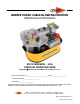
BREEZE MICRO CABLE BLOWING MACHINE OPERATION & MAINTENANCE 89010 (BREEZE) – USA CABLE BLOWING MACHINE Copyright 2009 by General Machine Products Co., Inc QC Final Inspection by:_________________________ Date:__________________ Unit Serial Number:__________________ Build Date:__________________ All rights reserved. No part of this publication may be copied, reproduced or transmitted in any form whatsoever without the written permission of General Machine Products Co., Inc.
REVISION HISTORY Rel.no Date Details Author 01 08.27.03 Original issue A. Sibun 02 09.19.07 US Version 1 A. Konschak 03 07.05.07 US Version 2 A. Konschak 04 04.30.08 US Version 3 A. Konschak 05 05.25.09 US Version 4 A. Konschak 06 11.23.09 US Version 5 - updated CUB5 Matrix A Konschak 07 06.09.10 US Version 6 - update Appendix 1 A Konschak 08 03.29.11 US Version 7 - update blown fiber page 24 A Konschak 09 05.18.
CONTENTS 1. Safety Instructions 2. Critical Points 3. General Description 4. Specification 5. Operating procedures 6. Maintenance 7. Procedure for changing inserts in the tube clamp 8. Procedure for changing inserts in the air box 9. Procedure for changing inserts in the infeed guide 10. Procedure for re-positioning the measuring system fixed roller 11. Procedure for replacing the air box housing seal 12. Procedure for changing the air box infeed guide 13. Procedure for changing the drive rollers 14.
1. SAFETY INSTRUCTIONS This Equipment should be used only by personnel who have been given the appropriate training and who are competent to use it. These instructions are to be made available to operators of this equipment at all times. Failure to observe these safety instructions could result in serious personal injury and/ or property damage. WORK AREA AND GENERAL SAFETY 1. Read and understand the operation and maintenance manual supplied with this equipment.
16. No personnel are to be in manholes or ducts when the Cable Blowing Machine is being operated. 17. The machine must be operated on firm ground. 18. Stay clear of cables or lines under tension. 19. Stay clear of pressurized air line and tube. 20. Only use the machine for its intended purpose. Do not use the roller drive without the air chamber to push or to retrieve cable or blow air in the far end of tube to help cable recovery. 21. Do not place cable drum too close to the Cable Blowing Machine. 22.
GENERAL PNEUMATIC SAFETY INSTRUCTIONS The GMP Fiber Optical Cable Blowing Machine is a pneumatic device, using pressurized air to project cable at high velocities. Please observe the following precautions when operating the Cable Blowing Machine: 1. Compressed air can cause flying debris. This could cause personal injury. Always wear personal protective equipment. 2. Insure no personnel are in the manhole at the far end of the cable run. Severe personal injury may result. 3.
2. Critical points that dramatically affect the operation of the cable blowing machine. Pressure on the cable (Position of the close arm assy) should be set as per the instructions. Rollers to be closed at all times when cable is installed into machine. Cord seals in air chamber correctly fitted to provide good sealing. Correct cable seal fitted. Tube fully connected and pressure-tested. Tube connecting fittings are suitable for operating at 220 PSI air pressure.
DISCLAIMER General Machine Products Co., Inc and CBS Products Ltd. takes care in the design of its products to insure that the cable is protected during installation. Due to the variety and different methods of cable manufacture the responsibility of checking the cable compatibility with the equipment lies with the user. Therefore, GMP nor CBS Products Ltd. can accept liability for any damage to the cable. Page 8 of 43 General Machine Products Co., Inc.
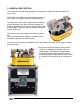
3. GENERAL DESCRIPTION The Breeze Micro Cable Blowing Machine is designed to install small diameter cable into micro tubes. The Breeze uses a DC motor and reduction gearing to drive a pair of compliant rollers that are both driven. The rollers are covered with a soft synthetic coating to prevent damage to the cable. Different coatings are available depending on the surface texture of the cable being installed. The rollers may be changed quickly using one simple tool.
4. SPECIFICATIONS Cable size: 1.0 to 8.5 mm1 0.1” to 0.335” Tube size: (OD) 4 to 18 mm 0.158” to 0.709” Cable speed: 0-50m/min. 0-165 ft/min Maximum pushing force: 16 Kg. 35 lbs. Maximum air pressure: 15 bar. 220 psi. Power requirements: 115/220V ac 50/60 Hz Switchable Gripping force, (rollers onto cable): 1-40 Kg 1-88 lb. Weight 23Kg approx. 50 lbs. approx. Dimensions (ht x length x width) 250mm x 390mm x 270mm 10” x 15 3/8” x 10 5/8” 1 1 - 2.
5. OPERATING PROCEDURE IT IS IMPERATIVE THAT ALL PERSONS USING, OPERATING OR MAINTAINING THIS CABLE BLOWING MACHINE: ● HAVE RECEIVED COMPREHENSIVE TRAINING IN THE USE OF THIS MACHINE. ● ARE COMPETENT AND AUTHORIZED TO USE IT AND HAVE READ AND UNDERSTAND THIS MANUAL. GENERAL MACHINE PRODUCTS CO., INC OR CBS PRODUCTS LTD. CANNOT BE HELD RESPONSIBLE FOR MISUSE OF THIS EQUIPMENT. Set up for installing cable with the machine mounted above ground: 1. Position the machine in line with the route of the duct. 2.
Fit the tube into which the cable is to be installed into the air box and tube clamp. Slide a tube seal, sized for the tubing you are using, over the end of the tube. Fit the tube about half way into the air box housing as shown in the photo, positioning the tube seal so that it sits against the seal face. Positioning the tube further into the air box helps prevent the bucking of smaller fiber. Once the tube has been positioned, the tube clamp may be closed. Securely tighten clamp with swing bolt.
Fit the cable through the machine. Loosen the thumb nuts and retract the cable guide top plate. Raise the clear cover to expose the roller drive. Loosen the thumb nut and open the seal housing. Hold back the measuring wheel, so that the spring is compressed. Move the drive roller close assembly to the far right to fully open the rollers. It is now possible to insert the cable in the machine.
Cable Guide Set top cover Seal Guide Half Split cable seal (see appendix 1) a. b. c. d. Close the air box. Close the cable guide set top cover. Release the measuring wheel and allow it to rest on the cable. Close the transparent cover. (note: This cover must be closed in order for the machine to operate) Close the drive roller assembly onto the cable as follows: The photo shows the drive roller close thumb nut slightly loosened. (The assembly is free to move).
The amount of pressure on the cable can be varied simply by loosening the thumb nut, moving the clamp arm lever to the right or left; as required, and tightening the thumb nut. As more experience is gained using the machine, the amount of compression required will become clear. Note: An alternative method of setting the compression force is detailed in the note at the end of appendix 2. Connect the air supply to the machine.
Set up for installing cable with the machine mounted below ground: The set up is similar to the set up for installing cable above ground, (described previously) typically this type of installation is demanded for “series blowing” i.e. when a length of cable is already installed, and the limit of installation distance is reached. In such cases it is customary to couple a “series machine” sited down a manhole some distance from the point of main installation.
Installing cable. The machine is fitted with a range of controls to help the operator to install cable in the minimum time with the least risk of causing damage to the cable or tube. These controls are identified and their function is described below. Speed Control Torque Control Emergency Stop Torque Range Switch Start Speed/Distance Indicator Torque control: This knob controls the motor torque, turn this clockwise to increase the torque (pushing force) applied to the cable by the rollers.
Start: This switch “arms” the emergency stop circuit. If the emergency stop button is used to stop the machine (whether in an emergency or not) it will be necessary to depress this switch before the machine will run again. Whenever the power to the machine is disconnected and reconnected, it will be necessary to depress this switch before the machine will run.
6. Maintenance The Cable Blowing Machine has been designed to give reliable, trouble free service over long periods. The machine requires no sophisticated maintenance procedures, simple common sense checks and precautions are all that are needed. The main source of breakdown and/or malfunction of a machine being used outdoors is contamination by the elements, this contamination may be introduced into the machine in a number of different ways.
Cable guide set parts: Keep clean. A build up of moisture and dust may catch the cable. This could cause the machine to stop feeding. Loosen the thumb nuts and slide back the top plate to expose the guide groove. Use any traditional workshop cleaning agent. Air box parts: Keep clean. A build up of moisture and dust will prevent the joint faces from mating, preventing the housing seal from sealing. Use any traditional workshop cleaning agent. Tube clamp inserts: Keep clean.
7. Procedure for changing inserts in the tube clamp Loosen the thumb nut, rotate the swing bolt to open the tube clamp Loosen and remove the two mounting screws. (Do not lose these screws, they will be needed for the replacement insert). Remove the insert Repeat the process for the insert in the other housing half To fit the new inserts, reverse the disassembly procedure. 8.
9. Procedure for changing inserts in the in-feed guide Loosen and remove the two screws securing the upper housing onto the lower housing Loosen and remove the screw securing the insert into the upper housing Remove the insert Repeat the process for the insert in the other housing half To fit the new inserts, reverse the disassembly procedure. 10. Procedure for re-positioning the measuring system fixed roller (It will be necessary to adjust the position of the roller.
11. Procedure for replacing the air box housing seal Spread adhesive along one side of cord. Apply a thin coat of 3M Rubber and Gasket Adhesive to the top of the cut sealing material Cut a length of 0.08inch sealing material 2 1/8” long (a little longer than is necessary). Place the pre-cut length in the groove, glue surface down, starting at the end with the retainer plate and aligning flush with the end of the groove.
12. Procedure for changing the seal guide halves Loosen and remove the two retaining screws. (Do not mislay these screws, they will be needed for the new seal guide half) Remove the seal guide half Repeat the procedure for seal guide half in the other housing half To install the new guides, reverse the disassembly procedure 13. Procedure for changing the drive rollers The machine is fitted with standard rollers, Tests have shown that these rollers give a good compromise of life and grip.
14. Blown Fiber Conversion (1.1mm, 1.6mm and 2.0mm) with 5mm Micro Duct Parts required for a 12 count blown fiber conversion are available in a kit form. In-Feed Guide Insert Set - 32877 Cable Guide Set 32875 Blowing Tips: • Insert a 2” piece of 5mm tubing in the InFeed Clamp Assy. • The measuring fixed roller should be adjusted so that just enough pressure is on the fiber to turn the measuring wheel without deflecting it. • Set the tube in the air box as shown in photo to right.
15. Monthly service – check list This section includes a list of suggested checks, it is recommended that these checks be carried out on a regular basis, depending on use. Monthly checks are convenient; a few minutes can be set aside on the same day of each month to complete these simple checks. The next section of this manual is an empty table, the dates when these checks and all other service and repair jobs are completed can be entered into the spaces provided in this table.
16. SERVICE HISTORY RECORD Service no Date Carried out by Page 27 of 43 Record of service/repair General Machine Products Co., Inc.
17. Tube integrity and Lubrication This is entirely the responsibility of the operator. To be sure that the tube into which the cable is to be inserted is installed appropriately, it is recommended that its integrity and lubrication be checked. Check that the tube is: 1. Not blocked 2. Not crushed 3. Continuous (no breaks) 4. Also check that any joins are pressure tight 5.
The air box and tube clamp are now set up to blow air through the tube. 1. Connect the air as for normal blowing. 2. Make sure there are personnel at the other end of the tube run, and that they are aware that the air is to be turned on. 3. Make sure that a suitable device is fitted to obviate injury should any object be expelled from the far end of the tube. 4. Apply air to the Breeze The far end of the tube run should be monitored; air should be leaving the tube under reasonable pressure.
18. Recommended spares list 1. 2. 3. 4. 5. 6. 7. Tube Seals Cable Seals Drive Rollers Cable end tips Lubricant Seal Cord 5 A and 325 mA fuses Note: See page 32 for part numbers or contact GMP customer service department. For spare parts always quote the machine type and serial number and contact: General Machine Products Co., Inc. 3111 Old Lincoln Highway, Trevose PA 19053 USA TEL: +1 215 357 5500 FAX: +1 215 357 6216 E-MAIL: info@GMPtools.com Website: www.GMPtools.
Page intentionally left blank Page 31 of 43 General Machine Products Co., Inc.
1. APPENDIX 1 This section lists the appropriate inserts, collets, etc required for a given cable/tube combination. The italicized numbers in the table are cable/tube identification numbers which are marked on the individual components. (Twelve count (1.6mm) conversion is found on page 25.) Cable size (O/D) Photo Infeed Guide Insert Set Seal Guide Half Set Cable seal (5/pk) Tube size (O/D) In-Feed Guide Set Micro Duct Seals (5 pk) Airbox Set Insert Clamp Set A B C 2.5-3.0mm 3.0-3.8mm 3.8-5.0mm 5.0-6.
2. APPENDIX 2 This section makes recommendations for the initial setting of the torque control potentiometer when installing a cable which has not been installed before, and, whose characteristics are unknown. The diagram to the left shows the torque and speed control knobs set in the maximum counter-clockwise position. In this position both torque and speed will be minimum. (Zero) The diagram to the right shows the torque and speed control knobs set in the maximum clockwise position.
The torque control setting will allow the cable to be installed efficiently and without damage. It is of vital importance that the torque setting is made with great care, a little time spent understanding the way to arrive at the optimum settings will save time and frustration during the installation. There are two stages to arriving at the correct torque setting they are described below. 1.
Torque Control Potentiometer Setting % of maximum rotation (clockwise) 1 U6 U5 0.75 U4 U3 U2 0.5 U1 0.25 0 1 10 Coefficeint of friction 3. Referring to the chart above. The “x” axis (the bottom line) represents the coefficient of friction; 1 is very low: 10 is very high. Look along this line from left to right. Pick a vertical line that is approximately the value of the coefficient of friction. Look vertically upward along this line.
Note: This method may also be used to set the clamping force of the rollers on the cable. Initially, the clamp arm lever should be set so that the rollers press very lightly onto the cable. Carry out the test outlined above (drive the cable into the closed end of a sample tube). The rollers will slip. Repeat this procedure, each time increasing slightly, the pressure the rollers apply to the cable. Eventually the rollers will stop turning because the torque limit has been reached.
3. APPENDIX 3 Programming Parameters for CUB5B counter/rate meter fitted to Breeze machines— Nov 2005 Onwards. The device must be wired and installed into the machine prior to programming. Breeze is fitted with C-M-DEV-CUB5B, backlight version. The DIP switch positions are as follows: 1 OFF 2 OFF 3 OFF 4 OFF Please see the attached CUB5 Programming Overview attached to this document. a. Press and hold SEL for 2 seconds to enter programming mode DIP Switch b.
Counter programming parameters for the Breeze machine: Press RST Once: Counter Parameters (1-INPUT) INPA-B = Cnt ud - if correct press SEL. CNT A DP = 0 - if correct press SEL CNT A SCF = 0.0102 (METRIC, m) or 0.
Page 39 of 43 General Machine Products Co., Inc.
Page intentionally left blank Page 40 of 43 General Machine Products Co., Inc.
GMP Limited Warranty 1a. General Machine Products Co., Inc. ("GMP") warrants to the purchaser and/or end user: (1) that a new product sold and manufactured by GMP will be free from original defects in material and workmanship for one year from the date the product was delivered to the purchaser and/or end user, or for the lifetime of the Modular Plug Presser; (2) that a new product sold and not manufactured by GMP will be covered exclusively by the manufac- turer's warranty.
4a. GMP products or parts which become part of a total assembly which has been designated and/or manufactured by others, are not covered by this Warranty unless GMP reviews the total assembly and expressly extends its warranty. 4b. Design, material and workmanship furnished by others to install or operate a GMP product or part are not covered by this Warranty with respect to GMP's products or parts which are used in that particular assembly. 4c.
GMP • 3111 Old Lincoln Hwy • Trevose, PA 19053 • USA TEL: +1-215-357-5500 • FAX: +1-215-357-6216 • EMAIL: info@gmptools.com Page 43 of 43 General Machine Products Co., Inc.