
Owner's manual

Page 30 of 40
General Machine Products Co., Inc.
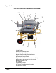
LAYOUT OF ROD PUSHING MACHINE
1 Rod Pusher
2 Sub-Duct Outfeed Clamp
3 Sub-Duct Infeed Clamp
4 Unit Lifting Point & Clamping Handle
5 Hydraulic Control Panel
6 Electronic Control Panel
7 Hydraulic Hose Connection (at rear of unit)
8 Emergency stop socket (on side of unit)
9 Frame Leveling Foot
10 Tool Box
11 Mounting Frame
12 Tractor Drive Movement Indicator
13 Directional Valve
1
2
3
4
5
6
7
8
9
10
11
12
Appendix 1
13