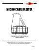
M ICRO CABLE FLEETER Operation and Maintenance Model 89002 All rights reserved. No part of this publication may be copied, reproduced or transmitted in any form whatsoever without the written permission of General Machine Products Co., Inc. General Machine Products Co., Inc. • 3111 Old Lincoln Hwy • Trevose, PA 19053 • USA TEL: +1-215-357-5500 • FAX: +1-215-357-6216 • EMAIL: info@gmptools.
REVISION HISTORY: Rev No. Date 01 11-2007 Original issue 02 6-2011 US Version Details Author A. Miller A.
CONTENTS 1.0 Introduction and Safety Instructions 2.0 General Description 3.0 Specification 4.0 Cable Threading and Operating Procedure 5.0 Equipment Layout 6.0 Spare Parts 7.
1.0 SAFETY INSTRUCTIONS THIS EQUIPMENT MUST ONLY BE USED BY AUTHORIZED PERSONNEL, WHO HAVE BEEN SUITABLY TRAINED AND COMPETENT TO DO SO THESE INSTRUCTIONS ARE TO BE MADE AVAILABLE TO OPERATORS OF THIS EQUIPMENT AT ALL TIMES. 1. Read and understand the operation and maintenance manual supplied with this equipment. Keep it in a convenient place for future reference. 2. Keep children and untrained personnel away from this equipment while in operation. 3. Keep all guards and safety devices in place.
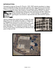
INTRODUCTION Founded by engineer George M. Pfundt in 1936, GMP started operations in a downtown Philadelphia building as a specialty machine shop doing work for the local Bell Telephone company and for the electric utility company. GMP expanded to a production shop after landing a contract with Western Electric Company and, subsequently, forming a close relationship with Bell Telephone Laboratories in Murray Hill, N.J.
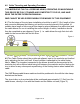
2.0 General Description The Micro Cable Fleeting Device has been developed to enable longer lengths of fiber optic cable to be deployed from a single drum. With the increasing trend of longer cable installations with more efficient cable blowing techniques there is a need for a Micro Cable Fleeting device. The need arises following the initial installation of the first half of the fibre optic cable from the drum.
3.0 Specification Cable diameter 5 – 8.5 mm (0.196” –0.334”) OD Max Cable Length 6500 Feet (2000 Meters ) Dimensions Basket Diameter 47.25” (1200 mm) Max. Width 50.6” (1825 mm) Height 55.
4.0 Cable Threading and Operating Procedure IT IS IMPERATIVE THAT ALL PERSONS USING, OPERATING OR MAINTAINING THIS DEVICE BE FULLY TRAINED AND COMPETENT TO DO SO, AND HAVE READ THE ENTIRE OPERATING MANUAL. GMP CANNOT BE HELD RESPONSIBLE FOR MISUSE OF THIS EQUIPMENT. 4.1 The first stage of the mid span installation should be to add 15’ (5m) length of tube and connector between the blowing unit and the innerduct placed in the ground.
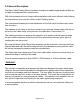
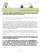
Figure 2 Undo the tube clamp and tube guide brackets in the fixed quadrant and unscrew and retract the adjustable rollers on the rotating carousel. Pull a suitable length of cable from the drum and through the 15’ piece of innerduct and insert the loop through the gap in the fleeter and clockwise around the central frame of the cable storage basket. See Fig 2. Clamp the innerduct, into tube clamp on the fixed quadrant. The tube can protrude through the clamp to within 1 to 1-1/2” (30-40 mm) of the rollers.
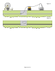
Figure 3 Figure 4 Page 10 of 14
5.
6.0 Spare Parts For spare parts contact: General Machine Products Co., Inc. 3111 Old Lincoln Hwy Trevose, PA 19053 Telephone No: 215-357-5500 Facsimile No: 215-357-6216 E-mail: Info@gmptools.
Page 13 of 14
GMP • 3111 Old Lincoln Hwy • Trevose, PA 19053 • USA TEL: +1-215-357-5500 • FAX: +1-215-357-6216 • EMAIL: info@gmptools.