
Manual

Page 11 of 64 General Machine Products Co., Inc.
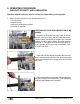
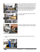
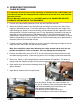
FEATURES
Fully labeled control panel containing:
• Power ON/OFF button (silver)
• Emergency Stop Button (red)
• Blowing speed read out in either ft/min or m/min through a separate calibration
• Length counter recording in feet or meters through a separate calibration
• Hydraulic pressure read out dial
• Air pressure read out dial
• Air pressure control lever
• Hydraulic on/off control valve
• Emergency stop connection socket
• Adjustable speed control for drive belts
• Battery Charging Connection
Control panels may be removed independently for repair work.
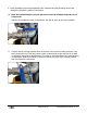
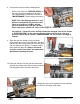
CHASSIS
• Front mounted wheels for ease of maneuverability
• Light painted tubular steel frame
• Adjustable frame allowing unit to be tilted at 20º to manhole
• Adjustable rear legs for uneven terrain
• Blowing unit is detachable from the trolley for trench / manhole location
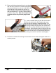
AIR BOX
• Manufactured from aluminum
• Range taking of cables from 6 - 32mm by means of interchangeable collets with double split
cable sealing arrangements.
• Sub-duct sealing at mouth of box
• Sub-duct gripping facility with non-duct crush and distortion design.
• All seals are one size cord seals (except cable seals)
• Upper section of air box is retained
• Air box alignment is adjustable for varying cable diameters
• Tools are not required to split box for insertion of cable and sub-duct.
• On/off air control valve
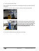
CABLE FEEDER
• Manufactured from cast aluminum
• Hydraulically powered
• Unit lifts and splits to allow insertion of cable between drive belts
• Drive belts are polyurethane and molded to unit ensuring long life between replacement.
• Lifting facility, to allow unit level lift.
• Belt tension can be set by means of adjustable chain drive tensioner fitted to side of unit
• System relief valve fitted as standard to operate at 1600 psi (110 Bar).