General Machine Products Co. 3111 Old Lincoln Highway · Trevose, PA 19053-4996 USA Tel: +1.215.357.5500 Fax: +1.215.357.6216 Email: info@GMPtools.com Web: www.GMPtools.
Installation, Operation and Maintenance Manual for the Adams® Model CD Lite Continuous Duty Winch manufactured by General Machine Products Co., Inc. Scope This document contains information pertinent to the Installation, Operation and Maintenance of the Adams® model CD Lite - Continuous Duty Winch. Such winches as manufactured by General Machine Products Co., Inc. commencing in June 1, 1995 were significantly different from the larger Adams model CD Winches in their equipment design and components.
1.03 WINCH CLUTCH GENERAL INFORMATION The clutch provides a means of transferring the torque from the drum shaft to the winch drum. When the winch clutch is disengaged, the drum will rotate freely on the drum shaft. Power can still be transmitted through the drum shaft to the optional drum shaft extension to drive a capstan or reel, if so equipped, while the clutch is disengaged. An air shift mechanism actuates the clutch plate in and out.
A counterbalance valve is a part of the brake system and helps to increase the responsiveness of the brake and improve the load control capabilities of the winch. The counterbalance valve and hoses are shipped loose in the parts box and require mounting and plumbing at the time of the winch installation. Refer to section 3.05. 1.06 WINCH MOTOR The winch drive consists of a hydraulic motor with a single 1.75 in. (44 mm) wide gear section.
to the curb side of the vehicle and is mounted on the winch drum shaft by means of a coupling secured by self-locking nuts. Designed with the conventional bayonet type of connection, it is suitable for driving a reel or capstan. To mount a device onto the shaft extension, slide the device spindle over the shaft extension, push all the way in, turn counter clockwise and pull out into the locked position.
of the winch line is properly spliced or swaged. Wire rope (winch line) may be old, damaged or weakened by such defects as kinks, cuts, extreme bends or loops. Such conditions are potentially dangerous and detrimental to safe operation of the winch. The wire rope must be routinely inspected at regular intervals and replaced when worn. See Maintenance Section 6.01 for replacement criteria. Loads on the winch, winch line or extension shaft should not exceed their rated capacity.
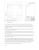
3. INSTALLATION 3.01 GENERAL - The following procedures are recommended to assure trouble-free operation: For typical automotive applications, the winch is normally mounted behind the chassis cab in the forward section of the body load area, directly to the chassis frame. Two steel mounting brackets are furnished with each winch. Sufficient clearance should be allowed between the front body panel or other restrictive members and the winch to permit normal maintenance.
Refer to drawing 26662 for recommended mounting hole locations. The factory does not supply mounting fasteners to attach the winch mounting brackets to the vehicle chassis. Recommended fasteners are four (4) 1/2 - 20 HHCS grade 8 bolts per each of the two mounting brackets for a total of eight fasteners per winch installation. Using a drill diameter 1/32 in. greater than the nominal bolt diameter, drill a clearance hole through the mounting brackets and through the truck chassis.
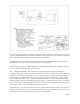
The control valve available from the factory as an option for the CD Lite winch has been selected specifically for this application. The internal piloted relief valve is pre-set at the factory, and needs no field adjustment. The porting on the control valve was selected to minimize the amount of reducing fittings needed.
tank; Control valve through power beyond to hydraulic system; Control valve work ports to winch motor ports. Suggested Filtration, based on the hydraulic motor requirements, is 20 to 30 micron (nominal) filters. Consult the filter supplier for specific filter recommendation. The hydraulic motor case drain (1/4 NPT) should be ported to tank. Identification of connections from the individual valve ports to the motor ports is shown in drawing 30575.
A terminal strip is provided for the electrical connection to the directional control valve. The terminal strip is located on the hanger assembly on the outboard side. A two position switch should be used to energize the solenoids in the directional control valve. The solenoids control the positioning of the valve spool thereby directing the airflow to the two ports on the air cylinder. There are eight screws on the terminal strip.
The sensors should be wired as per drawing 25777. The sensors detect the magnetic piston in the air cylinder and not the switch used to activate the directional control valve, so even manual actuation of the clutch is detected by the sensors. 3.04 CALIPER TYPE DRAG BRAKE - For reasons of safety and convenience, the drag brake is equipped with a remote actuator. The remote actuator, reservoir and flexible hose section are shipped loose with other winch mounting hardware in the parts box.
• • • Re-tighten the bleeder screws and allow the actuator to return. Repeat the cycle until actuator is firm. Make several static brake applications and then repeat the cycle once more. The closed circuit hydraulic system must not leak. Even the smallest leak could defeat what would otherwise be a well operating and effective brake system. It could eventually deplete the reservoir and reduce the braking pressure. To avoid leaks...
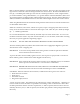
3.05 FULL LOAD BRAKE - Although the full load brake is factory installed, the mounting and plumbing of the brake counterbalance valve and the brake bleeding procedures must be followed during installation of the winch to ensure proper brake operation. 3.051 INSTALLATION OF THE BRAKE COUNTERBALANCE VALVE A counterbalance valve is a part of the brake system and helps to increase the responsiveness of the brake and improve the load control capabilities of the winch.
3.052 REQUIRED BLEEDING OF THE FULL LOAD BRAKE SYSTEM Bleeding the full load brake is required anytime air has been introduced into the system, and must always be performed by the dealer during the winch installation, in order to assure proper release of the brake for winch drum rotation. Bleeding is accomplished by pressurizing the system and loosening the bleeder screw on the top of the brake (shown on drawing 30578).
The brake is provided with a case drain. Should fluid leak into the brake housing, the case drain will open to let the fluid escape. If fluid leaks from the case drain, contact the factory for assistance. WARNING! THE FULL LOAD BRAKE MAY NOT HOLD THE RATED LOAD IF THE CASE DRAIN IS LEAKING FLUID. Any back-pressure in the tank return line may reduce the holding power of the brake. The brake is spring applied and hydraulically released.
right side) and the wire rope is spooled onto the winch drum at the bottom. As with any winch, it is imperative that the wire rope be attached to the correct side of the drum for the specific direction of the lay of the rope given the direction of drum rotation. When the drum will be underwinding as the wire rope is spooled in, use the rope clamp on the side of the drum which is opposite of the lay of the wire rope.
Engage the hydraulic pump drive and allow the oil to circulate and warm up for a few minutes before operating the winch. This is particularly important during extremely cold weather. Check operation of the drag brake. Check the body load area in a triangular section between the tail shelf sheave and both drum flanges for obstructions that could restrict the travel of the winch line or level wind. IMPORTANT! BEFORE THE WINCH IS ACTUATED, THE FULL LOAD BRAKE MUST BE BLED. See Section 3.05, INSTALLATION.
When finished with the winch and it is desired to stow the free end of the winch line, hook the winch line pulling eye to a fixed section of the chassis. A slight tension should be maintained in the winch line, preventing the formation of loose wraps on the drum. 6. MAINTENANCE 6.01 GENERAL - Inspection of the winch and related components should be a continuing procedure. The operator should be constantly alert to detect unusual noises, excessive oil leakage and overheating.
the oil level up to the level of the oil level plug opening in the side of the gearbox.. The oil will just start to run out of this opening when the proper level has been reached. Do not overfill the gearbox! The oil level plug in the side of the gearbox must always be removed before adding oil to avoid over-filling. When the correct oil level is reached, screw the oil level plug back into the side of the gearbox and screw the oil fill plug into the top of the gearbox.
6.03 WINCH IDENTIFICATION - Manufacturer or dealer assistance is available when needed to assist in resolving unique maintenance problems. When contacting your local dealer or the factory, proper assistance can be offered if the model and serial number of the winch in question is specified. This information is stamped on a nameplate affixed to the gearbox. 6.04 CALIPER BRAKE - It is recommended that brake hoses and brake lines be inspected regu- larly. All damaged or worn parts should be replaced.
AIR SHIFT CLUTCH AND CALIPER BRAKE—PARTS LIST Figure 1A ITEM 1 2 3 4 5 6 7 8 9 10 11 12 13 14 15 16 17 18 19 20 ITEM # 26857 26858 30485 26849 25678 25675 25868 30487 30484 30486 30553 17811 30479 26474 26588 26560 26590 17135 17136 17137 DESCRIPTION REQD.
DRUM GUARD—PARTS LIST ITEM 1 2 3 4 5 6 7 8 9 10 11 P/N 26716 26721 26715 26719 26718 26717 26871 25516 26720 26872 09940 DESCRIPTION DRUM GUARD PLATE GEAR BOX SIDE DRUM GUARD ROD DRUM GUARD PLATE HANGER SIDE SHORT SUPPORT SHAFT MEDIUM SUPPORT SHAFT HANGER SUPPORT SHAFT SCREW 5/16 X 3/4” FLAT HD. HEX BOLT 5/16-18 X 2” MOUNTING PLATE SCREW 5/16-18 X 5/8” BUTTON HD. NUT 5/16-18 ELASTIC STOP REQ'D.
MOTOR / FULL LOAD BRAKE / SHUTTLE VALVE PARTS LIST Figure 3A Item 1 2 3 4 5 6 7 8 9 10 11 12 13 14 15 16 P/N 27024 30557 30559 25369 26345 25362 25363 26587 25365 26892 26893 26890 27029 27030 26891 26894 Description MOTOR, SINGLE-SECTION HYDRAULIC FITTING, RIGHT HAND FITTING, LEFT HAND HOSE ASSEMBLY –4 BRAKE, FULL LOAD BLOCK, SHUTTLE VALVE CARTRIDGE, SHUTTLE VALVE BRACKET, SHUTTLE VALVE (NOT SHOWN) FITTING, 90º SAE FITTING, TEE SAE FITTING, PLUG SAE FITTING, STR. THD.
PARTS LIST FOR ADAMS CD LITE LEVELWIND Item Part # Dwg.
PARTS LIST FOR ADAMS CD LITE LEVELWIND (CONTINUED) Item Part # 40 41 42 43 44 26583 26839 26874 26493 26576 45 26581 46 47 48 49 50 51 52 26505 27040 26722 27041 26496 26878 26877 Dwg. # 26839 Commʹl 26493 26505 27040 26722 26496 Commʹl Commʹl Description Sprocket 9 Teeth, Second Reduction Cross Chain Guard Cap Screw Hex Hd.
1a. General Machine Products Co., Inc. ("GMP") warrants to the purchaser and/or end user: (1) that a new product sold and manufactured by GMP will be free from original defects in material and workmanship for one year from the date the product was delivered to the purchaser and/or end user, or for the lifetime of the Modular Plug Presser; (2) that a new product sold and not manufactured by GMP will be covered exclusively by the manufacturer's warranty.
3f. Incidental repair charges incurred by an authorized GMP dealer or end user to remove construction hardware, modify a vehicle or otherwise gain access to GMP's product or part, is a condition beyond GMP's control, and is not covered by this Warranty. 4a. GMP products or parts which become part of a total assembly which has been designated and/or manufactured by others, are not covered by this Warranty unless GMP reviews the total assembly and expressly extends its warranty. 4b.