Adams Model WG Worm Gear Winch INSTALLATION, OPERATION & MAINTENANCE P/N 70530 WG INTERMITTENT DUTY WINCH Copyright 2012 by General Machine Products Co., Inc All rights reserved. No part of this publication may be copied, reproduced or transmitted in any form whatsoever without the written permission of General Machine Products Co., Inc. GMP • 3111 Old Lincoln Hwy • Trevose, PA 19053 • USA TEL: +1-215-357-5500 • FAX: +1-215-357-6216 • EMAIL: www.gmptools.
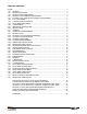
TABLE OF CONTENTS SCOPE ........................................................................................................................................ 3 1.00 GENERAL....................................................................................................................... 3 1.01 WINCH APPLICATION .................................................................................................... 3 1.02 WINCH MAJOR COMPONENTS .............................................................
SCOPE - This document contains information pertinent to the Installation, Operation and Maintenance of the Adams® Model WG Worm Gear Winch. The WG winch manufactured by General Machine Products Co., Inc. commencing in January 1, 2005 differ significantly from prior generations of Adams Winches in equipment design and components. To obtain information on earlier model CD, LCD or UG winches, please see our website at www.gmptools.com. 1.
The remote actuator, reservoir, and flexible hose section are shipped loose with other winch hardware in the parts box. These components are to be installed by the dealer or truck body builder. The closed circuit hydraulic system is shipped void of any fluid. Prior to operation, fill the system with only the exact type of fluid that was originally specified for your winch.
The drum shaft extension projects from the curb side (right) of the winch only. The required shaft length is determined by the width of the body. The maximum allowable pull of the standard drum shaft extension is 1,000 pounds (4,7 kN) using a standard 7 in. (18 cm) diameter capstan (GMP P/N 10727). Allowable pulls will be less when using a larger diameter accessory and/or using a longer drum shaft extension. 2.00 IMPORTANT PRECAUTIONS 2.
Wire rope (winch line) may be old, damaged or weakened by such defects as kinks, cuts, extreme bends or loops. Such conditions are potentially dangerous and detrimental to safe operation of the winch. The wire rope must be routinely inspected at regular intervals and replaced when worn. See Maintenance Section 6.01 on page 15 for replacement criteria. Make certain that the winch clutch is positively engaged before starting the pull. Operate the winch as smoothly as possible.
3.02 HYDRAULIC REQUIREMENTS - To obtain the maximum rated pull and line speed using the 2speed motor supplied with the WG winch, the hydraulic system shall have a rated flow of 20 GPM (75 l/ min.) maximum. Hydraulic system pressure shall be 1750 psi (12066 kPa) operating with 2000 psi (13790 kPa) maximum relief valve setting. The recommended hydraulic oil reservoir capacity for the WG winch is 60 gallons (227 liters) of petroleum-based hydraulic fluid.
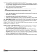
Recommended hydraulic line diameters are: ● Pump to control valve: 5/8 in. (16 mm) ● Control valve to tank: 5/8 in. (16 mm) ● Control valve through power beyond to hydraulic system: 5/8 in. (16 mm) ● Control valve work ports to hydraulic motor ports: 5/8 in. (16 mm) ● Pump to two-position, three-way selector valve for high speed feature: 1/4 in (6.4 mm) ● Two-position, three-way selector valve to pilot control valve for high speed feature: 1/4 in (6.
3.04 CALIPER TYPE DRAG BRAKE - For reasons of safety and convenience, the drag brake is equipped with a remote actuator. The remote actuator, reservoir and flexible hose section are shipped loose with other winch mounting hardware in the parts box. These components are to be installed by the dealer. 3.041 GENERAL GUIDELINES - Hydraulic brake components are precision built mechanisms and must be treated as such.
The importance of cleanliness during installation cannot be over-emphasized. ● Caliper Drag Brakes on Adams Winches may be specified by the customer for brake fluid only or hydraulic oil only. Installation and service personnel must verify which fluid to use for a specific winch, as the two different fluids are not interchangeable. Always use good, clean, quality fluid that conforms to what is specified on the brake components. ● Be sure all fittings and seats are clean before making connections.
3.05 WIRE ROPE INSTALLATION – When installing the wire rope, observe the following recommendations: Note: The WG winch is designed to accept 7/16” diameter wire rope only. It is important to select the correct winch and wire rope for a particular application. Wire rope is specified in terms of diameter, length, number of strands, number of wires per strand, composition of center core and direction of lay.
3.06 WINCH DRUM DIRECTION OF ROTATION - NOTE: The WG winch is only available in an UNDERWIND configuration. UNDER-WINDING – refers to the winch drum that rotates in a counterclockwise direction (viewing from the right side) and the wire rope is spooled onto the winch drum at the bottom. Once again, it is imperative that the wire rope be attached to the correct side of the drum for the specific direction of the lay of the rope given the direction of drum rotation.
4.02 WINCH BREAK-IN Winches, like any other kind of machinery, require a “break-in” to perform well and to maximize their life. The following guidelines should be used in the break-in of the WG winch. DO NOT exceed one half rated load or one half rated line speed for the first thirty minutes of operation. This will insure that the worm and gear have an opportunity to wear in properly. Periodically, check the gearbox for temperature rises and allow the winch to cool down between pulls. 5.
6.00 MAINTENANCE 6.01 GENERAL - Inspection of the winch and related components should be a continuing procedure. The operator should be constantly alert to detect clues to a potential problem such as unusual noises, excessive oil leakage or overheating. The operator should report immediately any changes in the normal characteristics of the winch, winch accessory or the hydraulic system.
The hydraulic system should be checked periodically for: ● Overheating ● Abnormal noise ● Maintaining a clean, sufficient, quantity of hydraulic oil of the proper grade. ● Keeping all connections sufficiently tight to prevent oil leakage and air from entering the system. ● Changing the hydraulic system oil filter at the frequency recommended by the filter manufacturer. IMPORTANT - THE LOAD HOLDING ABILITY OF THE LOAD HOLDING BRAKE SHOULD BE TESTED ON A PERIODIC BASIS. 6.
6.03 WINCH IDENTIFICATION - Assistance from the manufacturer or dealer is available to help resolve unique problems. When contacting your local dealer or the factory, the model and serial number of the winch in question should be specified so that proper assistance can be offered. This information is stamped on a nameplate affixed to the front mounting rail of the winch. 6.04 CALIPER BRAKE - It is recommended that brake hoses and brake lines be inspected regularly.
7.01 LEVEL WIND INTRODUCTION The level wind is a chain driven device specifically designed to distribute wire rope coils or wraps evenly across the winch drum. Level winding the wire rope onto the drum has several advantages: 1. Increases drum storage capacity 2. Prevents wire rope pile-up 3. Permits smooth, steady pulls 4. Makes accurate alignment of the truck with the pull unnecessary 5.
7.04 ADJUSTMENT The speed reducer input and output single width roller chain drives should be tight enough to prevent back lash but not excessively tight to cause bending of the reducer shafts. The triple width cross chain should be sufficiently tight to prevent tipping of the guide link. An unsteady movement of the carriage could indicate a loose cross chain or lack of lubrication on the guide bars.
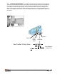
Details of Air Shift Clutch and Caliper Brake Mechanisms C D R L Q E A K B Key P/N Description Qty A 25677 Air Cylinder 1 B 28794 Air cylinder Mounting Block 1 C 25678 Air Directional Valve 1 D 25675 Regulator w/Schrader Valve 1 E 25767 Shifter Fork Stud 1 F 26243 Shifter Fork 1 G 25601 Bearing 2 H 25332 1/4 - 20 Elastic Stop Nut 2 J 28792 Clutch Plate 1 K 25333 1/2 - 20 Elastic Stop Nut 1 L 25634 3 - Pair Terminal Block 1 M 25828 Caliper Brake Ring 1
Page 20 of 28 www.gmptools.
Page 21 of 28 www.gmptools.
Page 22 of 28 www.gmptools.
Page 23 of 28 www.gmptools.
WG Winch Dimensions Note: example shown of a winch with a shaft extension sized for a 94” body. Page 24 of 28 www.gmptools.
Model WG Winch Specifications No other winch available anywhere offers you the same time-tested, rugged performance as the Adams winch. Now the best cable pulling winch your money can buy comes loaded with new performance features, and its more compact design takes up less than 25 in. of space on either side of the drum centerline with no sacrifice in capacity. What’s more, we’ve simplified the installation to give the Adams the lower installed cost compared to any other winch in its class.
1a. General Machine Products Co., Inc. ("GMP") warrants to the purchaser and/or end user: (1) that a new product sold and manufactured by GMP will be free from original defects in material and workmanship for one year from the date the product was delivered to the purchaser and/or end user, or for the lifetime of the Modular Plug Presser; (2) that a new product sold and not manufactured by GMP will be covered exclusively by the manufacturer's warranty.
4c. Hydraulic, pneumatic, electrical or mechanical control equipment which is not manufactured by GMP and which becomes a part of a GMP assembly, is not covered by this Warranty. 4d. This warranty does not cover a GMP product or part which others have subjected to abuse, improper installation, improper operation, alteration or negligence in storage or handling. 5a.
General Machine Products Co., Inc. 3111 Old Lincoln Highway Trevose, PA 19053 USA TEL: 215-357-5500 FAX: 215-357-6216 E-MAIL: info@GMPtools.com WEB: http://www.GMPtools.com GMP reserves the right, without notice, to make changes in equipment design or components as progress in engineering or manufacturing methods may warrant. All contents ©2010 GMP Page 28 of 28 www.gmptools.