Integrator’s Guide RIM 801D OEM Radio Modem version 1.
RIM 801D OEM Radio Modem Integrator’s Guide Last Revised: 22 February 1999 Part Number: MAT-01769-002 Rev. 001 © 1998, RESEARCH IN MOTION LIMITED Research In Motion and RIM are registered trademarks of Research In Motion Limited. DataTAC and RD-LAP are trademarks of Motorola. MS-DOS is a registered trademark, and Windows is a trademark, of Microsoft Corporation. Velcro is a registered trademark of Velcro Canada Incorporated. Scotchmate and Dual Lock are trademarks of 3M Corporation.
FCC Compliance Statement (USA) FCC Class B Part 15 This device complies with Part 15 of FCC Rules. Operation is subject to the following two conditions: 1. This device may not cause harmful interference, and 2. This device must accept any interference received, including interference that may cause undesired operation. Warning Changes or modifications to this unit not expressly approved by the party responsible for compliance could void the user’s authority to operate this equipment.
Contents FCC Compliance Statement (USA) .......................................... i Figures, tables and equations ................................................. v About this guide..................................................................... vii 1. Introduction ................................................................. 1 Radio modem features.....................................................................1 DataTAC network technology.....................................................
. Protocol support ........................................................ 33 Service Data Units (SDUs)........................................................... 34 NCL Protocol ............................................................................... 35 Radio Access Protocol (RAP) ...................................................... 35 Summary....................................................................................... 41 7. Interfacing and controlling the RIM 801D .............
Figures, tables and equations Figure 1: Top view of RIM 801D Figure 2: Side view of RIM 801D Figure 3: Battery Transmit Power Comparison Figure 4: Sample plug-in supply Figure 5: FPC cable and connectors Figure 6: Controlled Shutdown Using a Low-Power Battery Supply Figure 7: Connecting an antenna Figure 8: Different MMCX Connector Orientations Figure 9: Example SMA Jack Connectors Figure 10: RAP Frame Structure Figure 11: Sending data from the host to the wireless network Figure 12: Simple PC RS232 Interfa
About this guide This document is a guide to integrating the RIM 801D OEM DataTAC radio modem into an embedded system, such as a laptop computer, PDA, vending machine, POS terminal, or alarm system.
1 1. Introduction Topics covered in this introduction include the RIM 801D OEM radio modem features and an introduction to DataTAC network technology. Radio modem features The RIM 801D OEM radio modem is specifically designed to integrate easily into a computer or other embedded system, such as PDAs, vending machines, and point-of-sale terminals. Operating in the 800 MHz frequency range, the RIM 801D is compatible with DataTAC wide-area wireless data communication networks.
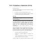
2 Introduction: Radio modem features Leveled Transmit Power 33.00 30.00 27.00 24.00 21.00 18.00 15.00 6.00 6.50 7.00 7.50 8.00 8.50 9.00 Battery Voltage [V] Noise immunity The RIM 801D is not de-sensitized by RF noise generated by nearby electronics. This makes the RIM 801D ideal for integration into hand-held terminals, and eliminates the need for special shielding.
Introduction: DataTAC network technology 3 DataTAC network technology The DataTAC infrastructure has become an international data communications standard, offering fast data transmission rates with accurate, highly reliable message delivery. DataTAC networks are deployed around the world from North America to Europe to Asia-Pacific. Using an advanced Radio Data Link Access Procedure (RD-LAP) radio channel protocol, DataTAC systems provide transmission rates up to 19.2 kb per second and 9.
4 Introduction: DataTAC network technology DataTAC Data System Station (DSS) base site equipment is located at various remote sites in the operational area of coverage and provides the RF link between the DataTAC infrastructure and end user devices. They convert the host data messages into the RD-LAP radio channel protocol for transmission to the user devices and reverse the process on the return connection.
2 2. Mechanical specifications and mounting needs This chapter provides information about the RIM 801D that will be useful in determining the physical positioning of the radio modem within an application. Environmental properties, case dimensions, cabling, connectors, and mounting suggestions are presented.
6 Mechanical specifications and mounting needs: Physical properties Physical properties Dimensions The RIM 801D has been designed to meet the most stringent space requirements. In most cases, there will be sufficient room in an existing enclosure to house the radio modem. Within the case of the modem, the smaller components are mounted on one side, and the larger components on the other. This separation of large and small components results in a case with two different thickness (see Figure 2, below).
Mechanical specifications and mounting needs: Physical properties 7 Figure 1: Top view of RIM 801D Figure 2: Side view of RIM 801D RIM 801D OEM Radio Modem – Integrator’s Guide
8 Mechanical specifications and mounting needs: Mounting the RIM 801D Mounting the RIM 801D The RIM 801D OEM radio modem may be securely fastened using a variety of methods. When deciding on a mounting option, the most important consideration is the operating environment. Such factors as extreme temperature or heavy vibration may dictate the need for a special mounting solution.
Mechanical specifications and mounting needs: Mounting the RIM 801D 9 Please be aware that because VHB is a permanent adhesive, the radio modem cannot be removed once it is installed. Attempting to break the adhesive bond by twisting off the radio modem will certainly damage the unit. There is no known solvent that will remove VHB. If using VHB as your adhesive, please make sure that you will not need to remove the radio modem after it is installed.
10 Mechanical specifications and mounting needs: Mounting the RIM 801D The RIM 801D can be removed and reattached as often as necessary using this method. • Attaching the RIM 801D to a flexible surface. Using Type 400 Dual Lock on both surfaces offers the maximum tensile disengagement of 55 psi (380 kPa). The RIM 801D can be removed and reattached as often as necessary using this method. • Maximum holding power.
3 3. Power requirements The RIM 801D OEM Radio Modem must be provided with a clean, high current power source. This can be provided by a plug-in power supply unit, a rechargeable battery pack, or single use batteries. RIM has conducted extensive research and has developed guidelines for integrators to follow when designing the power supply system for the RIM 801D OEM Radio Modem. ! Care should be taken when supplying power to the RIM 801D. Connecting with the wrong polarity will damage the radio.
12 Power requirements: Load specifications Power Design Maximum voltage without damage 10.5 Volts Maximum operating voltage 9.5 Volts Minimum operating voltage 6.0 Volts Maximum current (at 7.2V) 1.3 Amps Recommended fuse size (external) 3.0 Amps Total supply impedance recommended (external) 1.5 Ω (max) Recommended operating voltage range 7.0 to 9.0 Volts Load Profile Express mode (typical) 60 mA Standby mode (typical) 12 mA Transmit current drain typical (1.
Power requirements: Automotive supplies 13 Automotive supplies If you plan to power the RIM 801D from an automotive supply, extra protection must be included to protect the radio modem from the intense power fluctuations experienced when the automobile is started. A circuit comprising inductors, transorbs and voltage regulators should be used to ensure the radio modem is protected from these power fluctuations.
14 Power requirements: Single use batteries Single use batteries When using single use cells, RIM has found that only Alkaline cells provide the high current necessary for transmission. AA, AAA, and even square 9 Volt batteries provide an excellent power source. The following graph was generated by a simulator, not an actual radio modem; it depicts the various transmit capacities of some standard “off the shelf” batteries. The transmit current used for these tests was 1.25 Amps.
Power requirements: Plug-in supplies 15 Plug-in supplies A plug-in supply converts normal AC power (usually 110 volts or 220 volts) into a steady DC source that can be used instead of batteries. The plug-in supply must be designed to ensure voltage spikes, lightning, and other power fluctuations cannot damage the radio modem. RIM recommends a supply capable of providing 8 volts and 1.5 amps peak current. This can be accomplished by employing a 12 volt 1.5 amp peak (1.
16 Power requirements: Connecting the power source Transient voltage protection zener diodes, or other spike arrestor circuits, should also be added to keep the inputs within the limits given in the RIM 801D load specifications. These should have a value of 20 volts and be placed on the supply side of the regulator circuit. Connecting the power source Whatever the power source, it must be connected to the RIM 801D through the power input pins on the side of the radio modem.
4 4. Serial interface specification The serial interface on the RIM 801D operates at HCMOS electrical levels. This interface can be connected directly to a micro-controller, or through a UART to a microprocessor data bus. Signal specifications (Standard 5V interface) Outputs Output High Voltage @ 10µA 4.5 Volts Min. Output Low Voltage @ -10µA 0.4 Volts Max. Short Circuit Current 24 mA Max. Recommended Output Capacitance (To Filter Interface Lines) 390 pF Inputs Input High Voltage 3.5 Volts Min.
18 Serial interface specification: Connecting the serial cable Input Low Voltage 1.5 Volts Max. Input Leakage Current High 1.0 µA Input Leakage Current Low -1.0 µA The RIM 801D can also be customized for 3.3 volts. Connecting the serial cable The RIM 801D serial communication and power on/off signals are carried on a flat 14-conductor flexible printed circuit (FPC) cable, which can plug into a matching connector. An appropriate 4” 14-pin cable is available from Molex Canada, part number 88-00-8025.
Serial interface specification: Detailed pin description 19 Detailed pin description This section describes the purpose of each of the 14 lines that comprise the serial interface of the RIM 801D OEM radio modem. Note that any unused inputs should be tied to ground (with the exception of DNC1 and DNC2).
20 Serial interface specification: Detailed pin description RX Receive is an output from the radio unit to the host terminal’s Receive input. This is a TTL/CMOS compatible output that is short-circuit protected. This line can be connected directly to the input of almost any asynchronous communications IC. This line has an impedance of 1 kΩ and will be low when the radio unit is off. The idle (no data) state of this line is high.
Serial interface specification: Detailed pin description 21 DSR Data Set Ready is an output from the radio unit. This signal is electrically connected to the DTR input and will therefore have the same properties as the Host’s DTR output. When the Radio unit is off, this line will be low from inside the radio modem with an impedance of at least 20 kΩ. RTS Request To Send is an input to the Radio unit from the host. This line should be asserted low by the host to indicate that data is waiting to be sent.
22 Serial interface specification: Detailed pin description simply be left disconnected. This line has a built in current limit that allows it to drive an LED directly as visual feedback for a user. This line will supply 3 mA to a standard LED, and is short-circuit protected. This line is low when the Radio is off. ONI ON Indication is an output from the radio that indicates when the radio is on and operational.
Serial interface specification: Turning the radio ON 23 Turning the radio ON To turn on the RIM 801D, the software should first check the ONI pin. If ONI is high, but TURNON is being held low, then the radio is currently performing shutdown operations and should not be disturbed. Wait for ONI to go low before continuing. If ONI is low, this indicates the radio is in the off state. Set the TURNON line high to activate the unit. The ONI pin will respond by going high from 100 - 500 ms later.
24 Serial interface specification: Turning the radio OFF modem to terminal link, will not be saved. The SDU will be lost when the unit enters shutdown or is turned off. ! A controlled shutdown is necessary to allow the RIM 801D to tell the DataTAC network that it is off air. The following schematic offers a lowpower shutdown circuit, together with an example of using a 6-AA NiCad rechargeable battery pack to power the RIM 801D.
5 5. Antenna integration The choice of antenna is important to maximizing the coverage area of the RIM 801D radio modem. It is important to choose an antenna that will best compliment the needs of a specific project. There are many different antenna options that will meet both your gain and directivity requirements and remain within budget constraints. Three well-known antenna manufacturers that have experience with DataTAC frequencies are Larsen, Austin Antenna and Antenna Technology Inc.
26 Antenna integration: Antenna requirements radiator with a spherical radiation pattern. That is, the field energy density is identical in any direction from the radiator at each fixed distance from the radiator. Antennas produce gain by concentrating radiated energy in certain areas, and radiating less energy in other directions. Antenna match Antenna match is related to the Voltage Standing Wave Ratio (VSWR), a ratio of incident and reflected power due to impedance mismatch and antenna efficiency.
Interfacing and Controlling the RIM 801D Antenna integration: Positioning the antenna 27 Antenna efficiency The optimal antenna radiation efficiency is produced by a monopole. The best antenna length is the length of the wavelength, λ. Where f is the radio 8 frequency being used, λ= c/f ≈ 3x10 / f (metres). Antenna lengths of λ/2, λ/4 or λ/8 also work well and usually result in a relatively well matched antenna.
28 Antenna integration: Antenna cabling When the computing device is hand-held or is worn next to the body of the user, the antenna should be positioned to radiate away from the body. Otherwise, the effective coverage area of the radio will be reduced. Antenna cabling The RIM 801D radio modem must be connected to an antenna with a suitable low loss matching cable, with an impedance of 50 Ω.
Interfacing and Controlling the RIM 801D Antenna integration: Antenna cabling 29 RIM 801D Antenna Corner (Top-View) A B C Figure 8: Different MMCX Connector Orientations There are many orientation options available when connecting your antenna cabling to the RIM 801D. Figure 8 shows the top-view (as shown in Figure 1) of the antenna corner.
30 Antenna integration: Shielding (C) Flange Mount Cable Jack part number 2036-5003-02 (RG 142). Pictures of these three are shown below. Please refer to Appendix II for contact information for both M/ACOM and Huber&Suner. (A) (B) (C) Figure 9: Example SMA Jack Connectors RIM offers a comprehensive Developer’s Kit for the RIM 801D to assist system designers. Included in the kit is a 50 Ω antenna cable.
Interfacing and Controlling the RIM 801D Antenna integration: Shielding 31 frequency electrical noise, than to provide additional RF shielding between other computing devices and the RIM 801D case. The RIM 801D case provides shielding to prevent it from being affected by RF interference from the computing device to which it is attached. The case also prevents the RIM 801D from emitting RF energy into the computing device and disrupting the computing device’s operation.
6 6. Protocol support The RIM 801D OEM radio modem offers two link-level protocols: NCL (Native Control Language) and RAP (Radio Access Protocol). Both protocols serve the same function: they control the exchange of DataTAC data packets and radio control commands between the radio modem and the host device. RAP offers several advantages over NCL when used with the RIM 801D, or other applications where the radio modem is physically located close to the host device.
34 Protocol support: Service Data Units (SDUs) Service Data Units (SDUs) The DataTAC network transfers user data in packets called SDUs, short for Service Data Units. DataTAC Logical Link Identifier (LLI) The DataTAC Logical Link Identifier (LLI) is a 32-bit number which uniquely identifies each radio on a DataTAC network. This number is assigned by the DataTAC network operator, and is usually printed on the radio modem. An LLI is conceptually analogous to a telephone number.
Interfacing and Controlling the RIM 801D Protocol support: NCL Protocol 35 The user header consists of network routing information and is dependent on the particular network routing information being used. The DataTAC Open Protocol Specification on DataTAC Messaging (68P04025C10-O) contains information on user header formats for DataTAC networks.
36 Protocol support: Radio Access Protocol (RAP) When to choose RAP over NCL RAP helps application developers simplify software development on smallmemory devices like PDAs, vending machines, POS terminals, alarm panels, and other embedded systems. With NCL, the amount of software required to implement the NCL interface can be greater than the available memory.
Interfacing and Controlling the RIM 801D Protocol support: Radio Access Protocol (RAP) 37 • A radio configured to operate in RAP mode can detect certain NCL frames arriving on the serial port, and will automatically switch to operating as an NCL radio. The RIM Programmer’s Guide to RAP and SDU’s includes a complete protocol specification and contains detailed information about RAP frames and frame types. This information is summarized below.
38 Protocol support: Radio Access Protocol (RAP) checksum, the three trailer bytes must be received before the frame is accepted. ! Please make sure you understand that the RAP header, type, length, checksum, and trailer bytes are never transmitted to the wireless network. These bytes are used only in communication between the radio modem and the host device. Only the bytes contained in the DATA field are transmitted to the network.
Interfacing and Controlling the RIM 801D Protocol support: Radio Access Protocol (RAP) 39 RAP frame types Description Transmit SDU This indicates to the radio that the data is intended for transmission to the DataTAC network. Receive SDU The radio will send the host system the SDU that was received over the wireless network. Turn off radio This RAP frame type signals the radio to turn off. Power-save mode The radio will enter power-save operating mode as soon as it is able.
40 Protocol support: Radio Access Protocol (RAP) RAP frame types Description Request network name This frame causes the radio to send a Current Network Name reply. Current network name This is the radio’s reply to Request network name. Set battery charge rate This command has no effect on the RIM 801D except to set or clear the battery charging flag in the Radio status frame.
Interfacing and Controlling the RIM 801D Protocol support: Summary 41 Summary LLI is an access number used to identify a radio modem. Each radio modem on a wireless network is assigned a unique LLI. SDU is a packet of data that is exchanged between the RIM 801D OEM radio modem. and the DataTAC wireless network. NCL is a communication protocol that provides for the reliable transfer of information across the serial link connecting the RIM 801D to the host device.
7 7. Interfacing and controlling the RIM 801D The RIM 801D OEM radio modem is designed to be used easily in an embedded system. This chapter presents schematics for an RS232 interface, a micro-controller, and a serial port interface. The following schematics can be used as starting points for more complex designs. Interfacing to an RS232 device The RIM 801D serial interface operates at HCMOS electrical levels, making it compatible with many existing system designs.
44 Interfacing and controlling the RIM 801D: Controlling the RIM 801D Controlling the RIM 801D There are different approaches to integrating the radio modem, and these depend on the design of the embedded system. We have provided an example of a RIM 801D OEM integration using an 8051 micro-controller in Figure 13. The 8051 is configured with: • 32 K of ROM • 256 bytes of RAM • 4 lines to the RIM 801D • 28 general-purpose control lines that can be used for your control functions.
Interfacing and controlling the RIM 801D: Serial port interface 45 RIM 801D Figure 12: Simple PC RS232 Interface RIM 801D OEM Radio Modem – Integrator’s Guide
46 Interfacing and controlling the RIM 801D: Serial port interface 40 VCC 31 VCC ALE* 1 2 3 7 VCC GND GND PB TD TOL ST 5 RESET RST 6 RST 30 9 VCC EA ALE (RD) (WR) (T1) (T0) (INT1) (INT0) (TX) (RX) 19 11.059MHz GND 22pF 20 2.7 2.6 2.5 2.4 2.3 2.2 2.1 2.0 28 27 26 25 24 23 22 21 1.7 1.6 1.5 1.4 1.3 1.2 1.1 1.0 8 7 6 5 4 3 2 1 0.7 0.6 0.5 0.4 0.3 0.2 0.1 0.
: Serial port interface 47 RIM 801D Figure 14: 8250 Serial Port Interface RIM 801D OEM Radio Modem – Integrator’s Guide
Specifications The following is a summary of the RIM 801D OEM radio modem specifications. Power supply & typical current usage • • • • • • • Single power supply; operating range: 6.0 to 9.5 VDC (7.
50 Specifications: Serial port interface • Hardware flow control • Radio parameters stored at power down • Terminal devices may power-down while radio-modem remains operational Mechanical & environmental properties • • • • • • • • • Weight: 2.3 oz. (64g), including case Footprint: 3.5” x 2.6” (87.5 x 66mm) Thickness: 0.3” to 0.38” (7.5 to 9.
Glossary of terms Term: Meaning: c The speed of light. dB decibel. A measure of power, based on a logarithmic scale. Embedded System A computer without the normal display, keyboard, and disk drives of a PC. FPC Flexible Printed Circuit. The serial communication cable on the RIM 801D is made using this type of flat multiconductor wiring. Gain In this document, gain refers to increase/decrease in radiated power. LLI Logical Link Identifier. Each DataTAC radio modem has one unique LLI.
52 Glossary of terms: Serial port interface Term: Meaning: OEM Original Equipment Manufacturer. Usually implies that the “OEM product” is re-labelled with another manufacturer’s name. The RIM 801D is designed to be embedded in OEM terminals, PCs and data gathering equipment, and as such the equipment it is embedded in will not normally carry RIM’s name. OSI The Open Systems Interconnection model allows different systems, following the applicable standards, to communicate openly with each another.
Appendices Appendix I - Parts Company Name Part Description & Part Number 3M - Industrial Tape & Specialties Division [USA] VHB technical data sheet Part #: 70-0702-0266-1(104.5)R1 Reclosable Fasteners Part #: 70-0704-5609-3(833)JR Antenna Technology, Inc.
54 Appendices: Appendix I - Parts Company Name Part Description & Part Number Huber & Suner [Canada] EZ Flex 405 antenna cabling with right-angle MMCX and SMA connector Part #: 133REEZ4-12-S2/1699 SMA connector Part #: 25SMA-50-2-25/111 Larsen [USA] DataTAC Antennas M/ACOM [USA] SMA jack connectors for flexible cable (Straight Cable Jack) Part #: 2032-5007-02 (RG 142) SMA jack connectors for flexible cable (Bulkhead Feedthrough Cable Jack) Part #: 2034-5004-02 (RG 142) SMA jack connectors for flexi
Appendices: Appendix II - Company Directory 55 Appendix II - Company Directory Company Name Contact Information 3M - Industrial Tape & Specialities Division [USA] Tel: 1-800-227-5085 Antenna Technology, Inc.
Index A E ACC · 3 Antenna cable · 28 efficiency · 27 gain · 25 gain, maximizing · 27 MMCX connector · 28 physical location · 27, 30 requirements · 25 return loss · 26, 52 shielding · 30 SMA connector · 29, 52 VSWR · 26, 52 Embedded system · 51 environmental properties · 5 C Cables antenna · 28 serial · 18, 51 D DataTAC · 51 network components · 3 network technology · 3 transmission rates · 3 DSS · 4 Dual Lock · 9 H Humidity level · 5 I Interface about · 17 connecting to · 18 connecting to an RS232 de
58 Index: Appendix II - Company Directory reclosable fasteners · 9 requirements · 8 Mounting solutions other · 10 N NCL · 51 NiCad batteries · 13 NMC · 3 Noise FCC compliance statement · i noise immunity · 2 shielding · 30 O frame types · 38 introduction · 35 RD-LAP · 3 Reliability noise immunity · 2 RIM 801D battery life · 2 controlling · 44 features · 1 physical size · 2, 6 RNC · 3 RNG · 3 RS232 · 52 S Power supply about · 11 alkaline batteries · 14 automotive supplies · 13 connecting · 16 load spe