
User's Guide

User’s Guide SB320 Product Description
2110059 Rev 1.0 Proprietary and Confidential Page 87
2. \STATUS_OUT2: Transmitter
• Low (on) when the transmitter is keyed.
3. \STATUS_OUT3: Power Down OK (not yet implemented)
• When low (on), this indicates it is safe to remove power to the modem. This works
in concert with the \SHDN signal noted above.
Status Inputs
There are four TTL-level status input lines provided. There are currently no features that use these
inputs. They are managed within the modem and may be left floating.
9.5.4.2. Wireline and Voice Interface
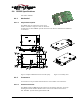
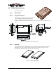
The SB320 provides a 13-pin I/O connector for its wireline interface. The connector is positioned
on the opposite end of the housing from the serial host (DTE) connector. This connector provides
these interfaces:
1. Telephone Line Interface
2. Status Outputs 1 and 2
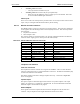
The connector pinouts are specified in Table 9-10. Specific configuration detail for the different
interfaces follow. Signal types are with respect to the modem (DCE).
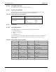
Table 9-10: Pinout of Wireline and Voice Connector
Pin number Signal Name Type Description
1 Reserved Leave Unconnected
2 SPKR– Output Speaker Interface negative
3 SPKR+ Output Speaker Interface positive
4 – 7 Reserved Input Leave Unconnected
8 \STATUS_OUT1 Output Power + RF Channel Status
9 \STATUS_OUT2 Output Transmitter
10 GROUND Ground Signal Ground
11 Reserved Leave Unconnected
12 RING Input Wireline Connection
13 TIP Input Wireline Connection
Telephone Line Interface
PSTN Line Connection
The telephone line interface consists of two signals: TIP and RING. These two lines should be
routed via a twisted-pair wire to a panel-mounted RJ-11 connector. The PSTN Load Number (5B)
is noted on the back label of the modem.
Note that is provides connection to analogue telephone lines only. Connection to digital PBX
lines is not supported.
Speaker Output
The speaker output is a differential signal used to interface to a speaker amplifier. The output
signal is AC-coupled 2 V
p-p
nominal into a 150 ohm load. In circuit-switched and wireline data
modes this signal is used to indicate call progress.
Status Outputs
These signals are the status outputs from the host interface brought out on the wireline/voice
connector. They are duplicates of the signals described in Section 9.5.4.1 above.