
User's Guide

The Hardware View SB300 Series
Page 86 Proprietary and Confidential 2110059 Rev 1.0
Operation in each mode is as follows:
• \RTS, \CTS
Used as standard hardware flow control lines.
• \DTR
Indicates to the modem that the host device is active. This line may also be configured to
switch the modem from data to command state or reset the modem (AT&D), and to enable
host wake-up. See the RI description below.
• \DCD
Is asserted in CDPD mode while online with an active session. Behaviour options in CSC
and Wireline modes are set with the command AT&C.
• \DSR
Always active when the modem is on; it is tied to logic GND.
• \RI
In Wireline and CSC modes, this line toggles when there is an incoming call (the telephone is
ringing).
In CDPD mode
Current application: The R1.0.1 firmware release for CDPD does not use the \RI signal. It
remains inactive.
Future application: If \DTR is inactive (high), \RI toggles when there is data for the host.
This may be used to wake-up the host.
The serial port should be configured for 8-data bits, no parity bits, and 1-stop bit. Although the
current firmware release (R1.0.1) is fixed at 19200 bps, the eventual default DTE configuration
will auto-baud to the host serial baud rate (based on speed of the ‘A’ in an AT command). Host
data rates of up to 115,200 bps will be supported. AT commands may be used to fix the baud rate
from 110 bps to 115,200 bps.
In Circuit-Switched mode data state and any mode’s command state, a terminal emulation
program may be used to communicate with the modem and change the configuration.
Modem Control Interface
Modem control is comprised of two inputs:
1. \SHDN: Graceful Shutdown
This is an active low input.
When activated this signal instructs the modem to de-register from the network, and
power down. When this activity is completed the \STATUS_OUT3 line is driven low
(on) indicating to the host that power may be removed from the device.
The modem must be powered down or reset before it is again ready for use.
2. \RESET: Hardware Reset
This is a hardware reset of the modem. This input should be externally pulled high and
driven low to reset.
Status Signal Interface
Status Outputs
There are three status outputs provided. These are active low and defined as follows:
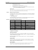
1. \STATUS_OUT1: Power, RF Channel Status
• Permanently low (on) when power is on but no cellular channel is acquired. This
output is high (off) when the modem is in CDPD and goes into logic sleep.
• Pulses low once per second with 10% duty cycle if modem has acquired a cellular
channel.
• Pulses low twice per second with 10% duty cycle if modem is registered on a CDPD
channel.