
User's Guide

The Hardware View SB300 Series
Page 80 Proprietary and Confidential 2110059 Rev 1.0
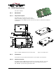
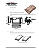
9.4.2.2. Host (DTE) Connector
The SB302 provides a single (2 x 8) 16-pin connector.
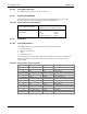
9.4.3. Power Specifications
The SB302 requires +5V provided on pins 1 and 2, and ground provided on pins 3 and 4.
Electrical requirements and current specifications are identified below.
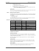
Table 9-4: Power and Current Specifications
Power Supply Requirements
+5V DC ±5%
Maximum noise DC to 100 kHz: 10 mV
pp
Current Drain
Deep Sleep: 12 mA
Sleep: 20 mA
Receive: 150 mA
Transmit (Full Power): 850 mA
9.4.4. Electrical
9.4.4.1. Host (DTE) Interface
The SB302 provides a single 16-pin connector that provides four interfaces:
1. Serial host interface
2. Modem control interface
3. Power
4. Status line interface
The connector pinouts are specified in Table 9-5, and electrical characteristics are specified in
Table 9-6 Serial Interface Electrical Characteristics. Signal types are with respect to the
modem (DCE).
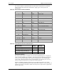
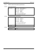
Table 9-5: Host Interface Connector Pinouts
Pin Number Pin Label Type Description
1 – 2 VBAT Input +5V
3 – 4 GND Ground Ground
5 TxD Input Transmit Data
6 RxD Output Receive Data
7 \DTR Input Data Terminal Ready
8 \DCD Output Data Carrier Detect
9 \DSR Output Data Set Ready
10 \CTS Output Clear To Send
11 \RTS Input Ready To Send
12 \RI Output Ring Indicator
13 \SHDN Input Graceful modem shutdown.
14 \STATUS_OUT1 Output Power + RF Channel Status
15 \STATUS_OUT2 Output Transmitter
16 \STATUS_OUT3 Output Power Down OK