
User's Guide


The Hardware View SB300 Series
Page 74 Proprietary and Confidential 2110059 Rev 1.0
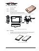
9.3.2. Connectors
See Section 9.2.5 for part number and manufacturer contact details on all connections.
9.3.2.1. Antenna Connector
The SB300 provides an MMCX type RF connector for the antenna connection. For proper
matching the antenna should be 50 ohms with a return loss of 10 dB or better between
824 - 894 MHz. System antenna gain should be 0 dB.
9.3.2.2. Host (DTE) Connector
The SB300 provides a single 30-pin ZIF connector with 0.5mm pin spacing. An appropriate Flat
Flex Cable is required to make the connection to the host.
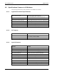
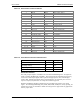
9.3.3. Power Specifications
The SB300 requires +5V DC provided on pins 23-24, and ground provided on pins 23-28.
Electrical requirements and current specifications are identified below.
Table 9-1: Power and Current Specifications
Power Supply Requirements
+5V DC ±5%
Maximum noise DC to 100 kHz: 10 mV
pp
Current Drain
Deep Sleep: 12 mA
Sleep: 20 mA
Receive: 150 mA
Transmit (Full Power): 850 mA
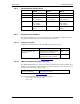
9.3.4. Electrical
9.3.4.1. Host (DTE) Interface
The SB300 provides a single 30-pin ZIF connector with 0.5mm pin spacing. This connector
provides four interfaces:
1. Serial host interface
2. Modem control interface
3. Power
4. Status line interface
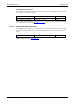
The connector pinouts are specified in Table 9-2, and electrical characteristics are specified in
Table 9-3 Serial Interface Electrical Characteristics. Signal types are with respect to the
modem (DCE).