
User's Guide


SB300 Series User’s Guide
Page 8 Proprietary and Confidential 2110059 Rev 1.0
2. Start the terminal application on the host PC. Configure the application for the port connected
to the MIB. At this time, the modem requires a setting of 19200 bps, 8 data, no parity, 1 stop,
with hardware (RTS/CTS) flow control.
3. Instruct the terminal application to connect.
The DTR and RTS indicators should be green. The TxD indicator should be red.
4. Attach the appropriate modem connector strap to the MIB port for the modem to be used.
• SB302 – 2x8-pin ribbon with connectors.
• SB300 and SB320 – 30-pin 5mm flex strap (without connectors).
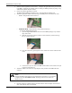
To make the SB300/320 connection:
i. Open the hinged SB300/SB320 connector on the MIB by lifting it away from the
edge of the board.
ii. Slide the strap into the connector with the contact side down (coloured side up).
Be sure it is fully inserted.
iii. Close the connector by pressing down on the ends of the connector rather than the
centre.
iv. Connect the 13-pin I/O cable to the MIB and the modem. This connector is keyed
to prevent connection error.
5. Attach the modem to the connector strap using the same procedure as the MIB end of the
connector.
NOTE
Although the MIB provides support for the full SB Series of modems, it is not intended
to support more than one modem at a time. Attaching more than one modem can
damage circuitry.
6. Place the antenna is a suitable location, attach the antenna connector adapter to the antenna
cable, and attach the cable to the modem.