
User's Guide

Getting Started
2110059 Rev 1.0 Proprietary and Confidential Page 7
2.3.2. Physical considerations
NOTE
The MIB and modem can be sensitive to static so the work surface should be a static
controlled environment.
2.3.3. Antenna considerations
The SB300 Series modem uses standard mobile cellular radio signals. An antenna (part
number 1810009) is provided with the OEM Developer’s Kit. Along with this antenna is a
connector adapter (part number 2000066) to convert the antenna connector (Male SMA) to match
the modem requirement (Male MMCX).
You can use an antenna of your own if you choose. Any standard cellular antenna of good quality
with a maximum system gain of 3 dB (FCC requirement) will function properly provided you
have a suitable connector.
Antenna performance is subject to the following guidelines:
Location – Locate the antenna as far away from personnel as possible to minimize signal
blocking. For optimum reception, in indoor fixed location applications, position the antenna
above the height of personnel and nearby equipment or structures. Locate the antenna as close to a
window as possible.
Cabling – Select a low loss, high quality, 50-ohm, coaxial cable with the appropriate connectors.
The cable can be any length, but lengths greater than 4 metres (13.1 feet) increase cable loss and
offset the antenna’s nominal gain. If longer length cables are required, use a heavier wire gauge to
reduce the dB loss/m and to minimize the effect of the cable loss on antenna gain.
Ground Plane – For installations where a good antenna ground plane (metal surface) is not
available, use a non-ground plane type of antenna to help maximize signal reception.
Proximity to Other Antennas – In general, do not locate the SB300 Series modem and its
antenna closer than 1.5 metres (5 feet) to another antenna. In certain cases even more separation is
required. The effect of the interference from two-way transmitters varies from slowing down
response times to blocking modem transmission.
2.4. MIB Presets
The Multipurpose Interface Board has several switches and jumpers which should be configured
as follows for the initial setup.
• DIP Switch in the Serial Breakout Box:
Switches 1 through 8 should be closed (on)
Switches 9 and 10 open (off).
• Power Select (J21) should be on pins 1 – 2 (+5V).
• HOSTSHDN, \SHDN, and MODEM DIS jumpers on J24 should all be off.
• Speaker Enable should be on.
2.5. Connections
This section describes the steps to connect the PC host, MIB, and modem. At the end of this
procedure you should be ready to configure and use the modem. If results at any step are not as
described, consult the chapter on troubleshooting.
To connect follow these steps:
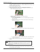
1. Attach the RS-232 serial cable from the host to the MIB PC Serial Port connector (J1).
The Serial Breakout Box indicators for DTR, TxD, and RTS should all light (powered from
the RS-232 connection).