
User's Guide

User’s Guide Multipurpose Interface Board
2110059 Rev 1.0 Proprietary and Confidential Page 97
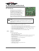
10.9. Initial Setup
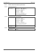
As shipped the MIB is configured as follows:
• Serial communication DIP switches are closed and the two spare switches are left open.
• Power select is on pins 1 and 2 to use MIB power for the modem.
• The following main jumpers are connected:
• ST IN1 – ST IN4 (Status Inputs to SB320) These are unused currently and simply
provide a “parking space” for jumpers which can be used as needed elsewhere.
• TP CTRL allowing for measurement of the MIB’s 5V power supply.
• The speaker is enabled.
The 5V power adjustment is set in the factory for 5V.