
User's Guide

User’s Guide Multipurpose Interface Board
2110059 Rev 1.0 Proprietary and Confidential Page 95
10.5.1.4. TP CTRL
Test Point 5 is tied to this jumper. When the jumper is removed, the test point delivers GND;
when the jumper is inserted it delivers the MIB’s 5V DC, independent of the modem’s power
supply.
10.5.1.5. MODEM DISBL
Placing a jumper on this pair of pins will disable the MIB’s conversion of the modem serial
connection from HCMOS level to RS-232 level, effectively disconnecting the modem from the
Serial Breakout Box and the host (both PC and direct SB302 host connection). Power and the
control signals \SHDN and \STATUS_OUT1 – 3 remain intact.
10.5.2. Power Select
A 3-pin block is provided to select the source of the +5V power supply to the modems. Placing
the jumper on pins 1 and 2 will connect the MIB’s regulated +5V supply. Placing the jumper on
pins 2 and 3 will connect the modem to power from the SB301/302 Host connection and remove
the trim pot.
The modem power switch comes AFTER the power selection jumper and can be used to control
power to the modems regardless of the source of the power.
10.5.3. SPK EN – Speaker Enable
A 2-pin block is provided to allow you to disable the speaker in situations where you would prefer
to mute the output. Placing the jumper on the pins will enable the SB320 to drive the speaker,
provided the SB320 I/O connector is in place.
The SB300 and SB302 modems do not provide speaker output. The SB320 speaker output is
driven through the wireline connector (SB320 I/O).
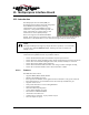
10.6. Serial Breakout Box
One of the main functions of the MIB is to provide a means of monitoring the serial connection
between a host and the modem. The MIB converts HCMOS level signals at the modem (and at
the SB301/302 Host connection) to RS-232 level for monitoring on the LEDs and with a protocol
analyzer.
In addition, the two rows of pins on each side of the DIP switch provide test points and
connections to each individual signal. This allows you to cross connect pins to correct cabling or
connector faults.
10.6.1. DIP Switch
The DIP switch is used to make or break the connection between the host and modem for each of
the serial communication signals. When switched to the open side, the connection is broken.
Should there be a cross connection error in the host / modem serial connection, switch off the
affected signals and use the breakout pins to bridge the signal correctly.
The last two switches are not connected.
10.6.2. Serial Connection Indicators
The LED indicators show the status of the serial communication on the modem side of the
breakout box. Red indicates an inactive signal, green indicates an active one. All LEDs are
labelled.