
User's Guide


The Hardware View SB300 Series
Page 88 Proprietary and Confidential 2110059 Rev 1.1
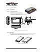
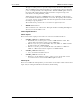
10.4.2. Connectors
See Section 10.2.4 for part number and manufacturer contact details on all connections.
10.4.2.1. Antenna Connector
The SB320 provides an MMCX type RF connector for the antenna connection. For proper
matching the antenna should be 50 ohms with a return loss of 10 dB or better between
824 - 894 MHz. System antenna gain should be 0 dB.
10.4.2.2. Host (DTE) Connector
The SB320 provides a single 30-pin ZIF connector with 0.5mm pin spacing. An appropriate Flat
Flex Cable is required to make the connection to the host.
10.4.2.3. Wireline Connector
The SB320 provides a single 13-pin I/O connector next to the antenna connector on the side
opposite the host (DTE) connector. This connector may require custom cabling.
The SB320 PSTN Load Number (5B) is shown on the back label.
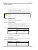
10.4.3. Power Specifications
The SB320 requires +5V DC provided on pins 23-24, and ground provided on pins 23-28.
Electrical requirements and current specifications are identified below.
Power-up timing for the modem requires that power ramp up at a minimum rate of 0.05 V/ms
within a maximum of 100ms. The ramp up should be graceful and linear (monotonic).
Table 10-5: Power and Current Specifications
Power Supply Requirements
+5V DC ±5%
Maximum noise dc to 100 kHz: 10 mV
pp
Current Drain Wireline Mode 220 mA
Current Drain CSC Mode
Receive: 220 mA
Transmit (Full Power): 850 mA
Current Drain CDPD Mode
Deep Sleep: 35 mA
Sleep: 45 mA
Receive: 220 mA
Transmit (Full Power): 850 mA
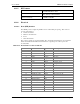
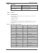
10.4.4. Heat Dissipation
The figures below indicate excess power dissipation beyond that radiated by the antenna.
Table 10-6: Power Dissipation Specifications
CDPD and CSC Transmitting at
Maximum Power
3.65 Watts
CDPD Logic Sleep 215 mW
Logic Deep Sleep 175 mW
CSC idle (receive) 1.25 Watts
Wireline 1.1 Watts