
User's Guide


The Hardware View SB300 Series
Page 84 Proprietary and Confidential 2110059 Rev 1.1
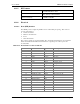
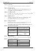
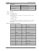
Table 10-4: Serial Interface Electrical Characteristics
Characteristic Min.(V) Max.(V)
Input Low Voltage -0.3 0.8
Input High Voltage 2.5 5.0
Output High Voltage (Ioh=400 µA) 2.4 –
Output Low Voltage (Iol=3.2 mA) – 0.5
Serial Port Interface
The serial port pins comprise a standard set of serial data and handshaking lines. All signals are
negative assertion, HCMOS logic compatible. These signals must be terminated properly if they
are not used. Unused input signals must be pulled to the appropriate in-active state through a
resistor (10k). Unused output signals may be left unterminated. If a signal may have use as an
input or an output (I/O) then treat it as an input for termination purposes.
Hardware handshaking should be enabled using \CTS and \RTS as the primary flow control
signals. The remaining handshaking lines (\DCD, \DTR, \DSR, and \RI) are, strictly speaking, not
needed; however they are desirable for TCP/IP stack usage and are supported for any applications
that may require them.
Operation in each mode is as follows:
• \RTS, \CTS
Used as standard hardware flow control lines.
• \DTR
Indicates to the modem that the host device is active. This line may also be configured to
switch the modem from data to command state or reset the modem (AT&D), and to enable
host wake-up. See the \RI description below.
• \DCD
Is asserted while online with an active session.
• \DSR
Always active when the modem is on; it is tied to logic GND.
• \RI
Using UDP or TCP packet service in CDPD, \RI toggles with a 1s on : 4s off duty cycle when
there is data for the host or a TCP connection request. If \DTR is inactive (high), the \RI
signal will go active through three cycles; otherwise it will go active once only. This is
repeated for each incoming packet or connection request until a session is opened. This signal
may be used to wake-up the host.
The serial port should be configured for 8-data bits, no parity bits, and 1-stop bit. Although the
current firmware release (R1.0.1) is fixed at 19200 bps, the eventual default DTE configuration
will auto-baud to the host serial baud rate (based on speed of the ‘A’ in an AT command). Host
data rates of up to 115,200 bps will be supported. AT commands may be used to fix the baud rate
from 110 bps to 115,200 bps.
In command state, a terminal emulation program may be used to communicate with the modem
and change the configuration.
Modem Control Interface
Modem control is comprised of two inputs:
1. \SHDN: Graceful Shutdown
This is an active low input.
When activated this signal instructs the modem to de-register from the network, and
power down. When this activity is completed the \STATUS_OUT3 line is driven low
(on) indicating to the host that power may be safely removed from the device.