
User's Guide


User’s Guide SB300 Product Description
2110059 Rev 1.1 Proprietary and Confidential Page 83
10.3.5. RF Features
Transmitter Power
nominal 600 mW into 50 Ω
Transmitter Performance Meets or exceeds CDPD V1.1 Section 405
FCC, Industry Canada, IS19B/C
Receiver Sensitivity -108dBm 5% BLER
10.3.6. Electrical
10.3.6.1. Host (DTE) Interface
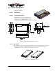
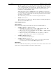
The SB300 provides a single 30-pin ZIF connector with 0.5mm pin spacing. This connector
provides four interfaces:
4. Serial host interface
5. Modem control interface
6. Power
7. Status line interface
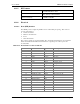
The connector pinouts are specified in Table 10-3, and electrical characteristics are specified in
Table 10-4 Serial Interface Electrical Characteristics. Signal types are with respect to the
modem (DCE).
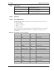
Table 10-3: Host Interface Connector Pinouts
Pin Number Pin Label Type Description
1 \DCD Output Data Carrier Detect
2 RxD Output Receive Data
3 TxD Input Transmit Data
4 \DTR Input Data Terminal Ready
5 GND Ground Ground
6 \DSR Output Data Set Ready
7 \RTS Input Ready To Send
8 \CTS Output Clear To Send
9 \RI Output Ring Indicator
10 \RESET Input Hardware Reset
11 Reserved Leave unconnected
12 \SHDN Input Graceful modem shutdown.
13 \STATUS_OUT1 Output Power + RF Channel Status
14 \STATUS_OUT2 Output Transmitter Key
15 \STATUS_OUT3 Output Power Down OK
16 STATUS_IN1 Input
17 STATUS_IN2 Input
18 STATUS_IN3 Input
19 STATUS_IN4 Input
20 – 22 Unused Allowed to float
23 – 24 VBAT Input +5V
25 – 28 GND Ground Ground
29 Unused Allowed to float
30 Reserved Leave unconnected