
User's Guide

SB300 Series User’s Guide
Page 8 Proprietary and Confidential 2110059 Rev 1.1
2.4. MIB Presets
The Multipurpose Interface Board has several switches and jumpers which should be configured
as follows for the initial setup.
• DIP Switch in the Serial Breakout Box:
Switches 1 through 8 should be closed (on)
Switches 9 and 10 open (off).
• Power Select (J21) should be on pins 1 – 2 (+5V).
• HOSTSHDN, \SHDN, and MODEM DIS jumpers on J24 should all be off.
• Speaker Enable should be on.
2.5. Connections
This section describes the steps to connect the PC host, MIB, and modem. At the end of this
procedure you should be ready to configure and use the modem. If results at any step are not as
described, consult the chapter on troubleshooting.
To connect follow these steps:
1. Attach the RS-232 serial cable from the host to the MIB PC Serial Port connector (J1).
The Serial Breakout Box indicators for DTR, TxD, and RTS should all light (powered from
the RS-232 connection).
2. Start the terminal application on the host PC. Configure the application for the port connected
to the MIB. At this time, the modem initially requires a setting of 19200 bps, 8 data, no
parity, 1 stop, with hardware (RTS/CTS) flow control.
3. Instruct the terminal application to connect.
The DTR and RTS indicators should be green. The TxD indicator should be red.
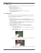
4. Attach the 30-pin flat flex modem connector strap to the MIB’s SB300/SB320 port.
To make the SB300/320 connection:
i. Open the hinged SB300/SB320 connector on the MIB by lifting it away from the
edge of the board.
ii. Slide the strap into the connector with the contact side down (coloured side up).
Be sure it is fully inserted.
iii. Close the connector by pressing down on the ends of the connector rather than the
centre.
iv. Connect the 13-pin I/O cable to the MIB and the modem. This connector is keyed
to prevent connection error.