
User's Guide


The Hardware View SB300 Series
Page 102 Proprietary and Confidential 2110059 Rev 1.1
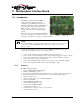
11.7. Test Points
There are six test points plus a pair of pins for current measurement. The sixth test point is not
used at this time.
11.7.1. TP1 DISC
This test point receives its signal from pin 30 of the SB320 modem connector and pin 1 of the
SB320 I/O connector. It presents the discriminator output of the radio modem.
11.7.2. TP2 KEY
All modem connectors provide the transmitter key indicator here. This signal is also indicated by
the S02 status LED.
11.7.3. TP3 5V Adjusted
The power output after the 5V ADJ trim pot can be measured here.
11.7.4. TP4 5V Setting
This test point is for factory presets only.
11.7.5. TP5 Debug for 5V / GND
This is connected to the TP CTRL jumper of the main jumper block and is available for debug
testing the MIB’s power supply. When the jumper is removed, the test point delivers GND; when
the jumper is inserted it delivers the MIB’s 5V DC, independent of the modem’s power supply.
11.7.6. TP6 Unused
Connected to the SB320 pins 20, 21, and 22, these signals are currently unused.
11.7.7. Current Measurement
Two pins are made available at J26 (Current Measurement) to allow calculation of the current
drawn by the modem. The calculation is based on V = I x R, where V is the measured voltage and
R is a known resistance (0.1 ohm). This formula reduces to I = 10 x V.
Measure the Voltage across the two pins. This is typically greater than 1 mV and less than 90 mV.
The current being drawn, in mA, is equivalent to 10 times the voltage measured in mV.
11.8. Reset Button
The reset button sends the reset control signal to the SB300 and SB320 connectors. The SB302
does not support a reset input signal.