
User's Guide


User’s Guide SB320 Product Description
2110059 Rev 1.1 Proprietary and Confidential Page 93
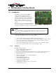
Telephone Line Interface
PSTN Line Connection
The telephone line interface consists of two signals: TIP and RING. These two lines should be
routed via a twisted-pair wire to a panel-mounted RJ-11 connector. The PSTN Load Number (5B)
is noted on the back label of the modem.
Note that is provides connection to analogue telephone lines only. Connection to digital PBX
lines is not supported.
Status Outputs
These signals are the status outputs from the host interface brought out on the wireline/voice
connector. They are duplicates of the signals described in Section 10.4.6.1 above.
10.4.7. SB320 Communication Mode Specifications
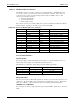
10.4.7.1. Wireline Specifications
Wireline Data CCITT V.34: 33600 – 2400 bps
CCITT V.32bis: 14400, 12000, 7200 bps
CCITT V.32: 9600, 4800 bps
CCITT V.22bis: 2400 bps
CCITT V.22: 1200 bps
CCITT V.21: 300 bps
Bell 212A/103: 1200, 300 bps
V.42 error correction (LAPM and MNP)
V.42bis and MNP5 data compression
Wireline Voice
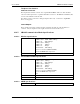
10.4.7.2. Circuit-Switched Data Specifications
CSC Data CCITT V.34: 16800 – 2400 bps
CCITT V.32bis: 7200 bps
CCITT V.32: 9600, 4800 bps
CCITT V.22bis: 2400 bps
CCITT V.22: 1200 bps
CCITT V.21: 300 bps
Bell 212A/103: 1200, 300 bps
V.42 error correction (LAPM and MNP)
V.42bis and MNP5 data compression
ETC
CSC Voice EIA/IS-19-B
CSC General IS-91 (future firmware revision)
10.4.7.3. CDPD Specifications
CDPD Version CDPD 1.1