
User's Manual
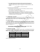
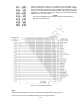
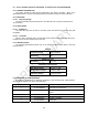
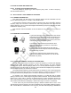
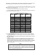
Table Of Contents

4-34
With the transceiver set-up in the meter-mode per Paragraph 2-3.1.5.,
pressing the [R/T] key will display the voltages of the internal power supplies
and of the batteries. The first time [R/T] is pressed the voltage of the +5Vdc
supply - PS1 is displayed. Each consecutive press of [R/T] brings up the next
supply; PS2: +12Vdc, PS3: -5Vdc, PS4: -12Vdc, PS5: +24Vdc (external power
batteries), PS6: +70Vdc and AGC.
NOTE
The AGC level displayed is not a voltage. The AGC is expressed as a
digital value from 000 to 255.
Figure 4-4. Breakout Box Schematic
Note:
When performing the Receiver Tests in accordance with Paragraph 4-2.2 and Figure 4-1:
● For the PT OUT on pin E of the Breakout Box, Pin D is the ground return.