
User's Manual
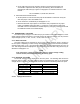
Table Of Contents

4-29
NOTE
When measuring AM transmitter output power on the R2600 or
on any power meter that has a peak detector, which includes
virtually all of the portable inline or direct power meters, the
carrier power that is read on the wattmeter will need to be
converted to average power to verify compliance as indicated
above. To convert carrier power to average power use the
following formula:
P
AVG
= P
C
[1 + (m
2
/ 2)]
where:
P
AVG
= Average Power
P
C
= Carrier Power
m = modulation as a decimal; i.e., 80% = .8
It should be noted, that in order to obtain the modulation value
for the above formula, the next step (c) will need to be
completed.
c. Read the AM % modulation on the R2600 screen. Verify compliance with Table 1-1 in
Section 1 of this manual.
d. Depress the DISP key on the R2600 front panel. Move the cursor to the Meter position and
press the "EXT DIST" softkey. Note: The "more" softkey may have to be depressed for
the "EXT DIST" softkey to be displayed. Read the % of distortion on the R2600 screen.
Verify compliance with Table 1-1 in Section 1 of this manual.
e. Unkey the URC-200 (V2) and adjust it for HI POWER. Depress the DISP key on the R2600
front panel. Move the cursor to the Meter position and press the "RF DISPLAY" softkey.
Note: The "more" softkey may have to be depressed for the "RF DISPLAY" softkey to
be displayed. Rekey the URC-200 (V2) and verify compliance with Table 1-1 in Section
1 of this manual.
NOTE
When measuring AM transmitter output power on the R2600 or
on any power meter that has a peak detector, which includes
virtually all of the portable inline or direct power meters, the
carrier power that is read on the wattmeter will need to be
converted to average power to verify compliance as indicated
above. To convert carrier power to average power use the
following formula:
P
AVG
= P
C
[1 + (m
2
/ 2)]
where:
P
AVG
= Average Power
P
C
= Carrier Power
m = modulation as a decimal; i.e., 80% = .8
It should be noted, that the modulation has to be measured in
order to obtain the modulation value for the above formula.
f. On both the URC-200 (V2) and the R2600 repeat steps A through E for preselect
channels 2 through 9 and channel 0 on the URC-200 (V2) with the R2600 set on
preset channel 10.
4-2.3.5 AM CT % Modulation and CT Distortion
1. Set up the test equipment as shown in Figure 4-2. Connect the
VERT/SINAD/DIST/DVM/COUNTER IN connector to the DEMOD connector on the
R2600. On the R2600 connect the MOD OUT connector to pin B of the X-MODE
connector on the URC-200 (V2). Do not connect the PTT (Push-to-Talk) line (pin F) to
ground. Note: When the PTT line is grounded the URC-200 (V2)'s transmitter will key itself
ON.
2. Set the input power supply to 28 .1 Vdc.
3. Preset the R2600 by performing the following steps.