
User's Manual
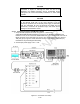
Table Of Contents

4-22
m. Move the cursor to the Horiz (Horizontal) position and depress the "500 us" softkey.
Note: The "more" softkey may have to be depressed for the "500 us" softkey to be
displayed.
n. Move the cursor to the Vert (Vertical) position and depress the "200 mV" softkey. Note:
The "more" softkey may have to be depressed for the "200 mV" softkey to be
displayed.
o. Move the cursor to the Pos (Position) position and depress the "move up" or "move
down" softkeys as appropriate to center the displayed scope screen trace. Note: The
TUNING knob on the R2600 panel may be used in lieu of the "move up" or "move
down" softkeys.
p. Adjust both the SQUELCH and VOLUME controls on the front panel to their maximum
CCW positions.
5. Setup the URC-200 (V2) as follows:
a. Turn the transceiver on and note the input current. It should be approximately 240mA.
If the current exceeds 330mA, a problem exists in the transceiver. Turn off the power
and troubleshoot the transceiver.
b. Set the frequency presets as listed in Table 4-3 on the URC-200 (V2). For each preset
channel, adjust the URC-200 (V2) for the following. Note: Information on presetting the
URC-200 (V2) is given in Paragraph 2-3.2 located in Section 2 of this manual.
FM, LO POWER, PT, SCN OFF, BCN OFF
6. Transmitter Frequency Accuracy and FM Power Output Measurements:
a. Set the presets on both the URC-200 (V2) and the R2600 to channel 01. Verify the
URC-200 (V2) is in the LO POWER mode.
b. Key the transceiver into the R2600 test set and read the frequency error displayed on
the screen. Verify the ppm as listed in Table 1-1 in Section 1 of this manual is within
compliance by dividing the frequency error by the operating frequency. Note: In keying
the transceiver the PTT line, pin F, will be grounded.
c. Measure the transmit power on the R2600 screen. Verify compliance with Table 1-1 in
Section 1 of this manual.
d. Unkey the URC-200 (V2) and adjust it for MED POWER. Rekey the URC-200 (V2) and
verify compliance with Table 1-1 in Section 1 of this manual.
e. Unkey the URC-200 (V2) and adjust it for HI POWER. Rekey the URC-200 (V2) and
verify compliance with Table 1-1 in Section 1 of this manual.
f. On both the URC-200 (V2) and the R2600 repeat steps A through E for preselect
channels 2 through 9 and channel 0 on the URC-200 (V2) with the R2600 set on
preset channel 10.
4-2.3.2 FM PT Deviation and Distortion
1.
Set up the test equipment as shown in Figure 4-2. Connect the
VERT/SINAD/DIST/DVM/COUNTER IN connector to the DEMOD connector on the
R2600. On the R2600 connect the MOD OUT connector to pins H and J of the X-MODE
connector on the URC-200 (V2). Note: Use Pin J as the return line, ground. Do not
connect the PTT (Push-to-Talk) line (pin F) to ground. Note: When the PTT line is
grounded the URC-200 (V2)'s transmitter will key itself ON.
2. Set the input power supply to 28 .1 Vdc.
3. Preset the R2600 by performing the following steps.
a. Press the MEM (Memory) key on the R2600 panel for the preset-screen.
b. Use the CURSOR POSITION keys to highlight preset 01.