
User's Manual
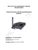
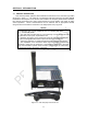
Table Of Contents

LIST OF ILLUSTRATIONS
Figure Page
iv
Figure 1-1. URC-200 (V2) Transceiver Set.................................................................................. 1-1
Figure 1-2. URC-200 (V2) Minimum System Requirement.......................................................... 1-6
Figure 1-3. Mechanical Configuration ........................................................................................ 1-11
Figure 2-1. URC-200 (V2) Front and Rear Panel Controls, Indicators and Connectors............. 2-2
Figure 2-2. Key-pad and Display Functions ................................................................................. 2-4
Figure 3-1. Remote-Control Unit .................................................................................................. 3-4
Figure 3-2. URC-200 (V2) Interfaces ......................................................................................... 3-23
Figure 4-1. Receiver Test Equipment Setup ................................................................................ 4-3
Figure 4-2. Transmitter Test Setup ............................................................................................ 4-20
Figure 4-4. Breakout Box Schematic.......................................................................................... 4-34