
User's Manual
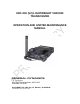
Table Of Contents

TABLE OF CONTENTS
Paragraph Page
iii
4-2.3.5
................................................ 4-29 AM CT % Modulation and CT Distortion
4-2.3.6
................................................................................................... 4-31 Beacon
4-3.
..................................................................................................... 4-33 Power Supply Voltages
4-3.1.
......................................................................................................... 4-33 Input Voltage
4-3.2.
.................................................................................................... 4-33 Internal voltages
4-3.2.1
.......................................................................... 4-33 Voltage Measurements
SECTION 5.
........................................................................................................... 5-1 OPTIONS
5-1.
......... 5-1 30 TO 90 MHZ OPTION 01-P37200N001 TO THE URC-200 (V2) TRANSCEIVER
5-1.1.
................................................................................................. 5-1 General Information
5-1.2.
.................................................................................................................. 5-1 Features
5-1.2.1
................................................................................... 5-1 Frequency Range:
5-1.2.2
.......................................................................................... 5-1 Tone Squelch:
5-1.3.
............................................................................................................... 5-1 Limitations
5-1.3.1
............................................................................................... 5-1 Modulation:
5-1.3.2
........................................................................ 5-1 Carrier-to-Noise Squelch:
5-1.3.3
.................................................................................. 5-1 Select Meter Mode:
5-1.3.4
................................ 5-1 UEC-120/220 Remote Control Optional Accessory:
5-1.4.
.......................................................................................................... 5-1 Specifications
5-1.5.
................................................................................... 5-2 Required System Equipment
5-1.6.
....................................................................................... 5-2 Installation And Operation
5-1.6.1
....................................................................................................... 5-2 Siting:
5-1.6.2
................................................................................ 5-3 Antenna Installation:
5-1.6.3
.................................................................. 5-3 Selecting LVHF Frequencies:
5-1.6.4
................................................................................................... 5-3 Squelch:
5-2.
..... 5-4 400 TO 420 MHZ OPTION 01-P39234N001 TO THE URC-200 (V2) TRANSCEIVER
5-2.1.
................................................................................................. 5-4 General Information
5-2.2.
.................................................................................................................. 5-4 Features
5-2.2.1
................................................................................... 5-4 Frequency Range:
5-2.3.
............................................................................................................... 5-4 Limitations
5-2.3.1
............................................................................................... 5-4 Modulation:
5-2.3.2
............................................................................................... 5-4 Text Mode:
5-2.4.
.......................................................................................................... 5-4 Specifications
5-2.5.
................................................................................... 5-4 Required System Equipment
5-2.6.
....................................................................................... 5-5 Installation And Operation
5-2.6.1
.................................................. 5-5 Selecting 400 to 420 MHz Frequencies:
5-3.
............................................................... 5-5 ECS- 8 OPTION - Part number 01-P42311K001
5-3.1.
................................................................................................. 5-5 General Information
5-3.2.
........................................................................................... 5-5 enabling Aviation mode
5-3.3.
......................................................... 5-5 tuning and channel spacing in aviation mode
5-3.4.
........................ 5-6 Tuning Increment Vs. Channel Spacing, Electrical Characteristics