
User's Manual

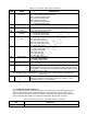
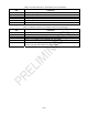
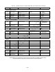
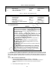
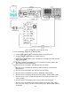
Table Of Contents

4-1
SECTION 4. SYSTEM MAINTENANCE
4-1. GENERAL INFORMATION
This section provides a system-level performance test to check all operations of the URC-
200 (V2) Radio Set. The following are also provided:
Procedures to localize a malfunction to a defective module.
Procedures for removal and replacement of all replaceable modules.
List of required tools and test equipment.
NOTE
This section does not include system-level performance tests to
check the various URC-200 (V2) options listed in Paragraph 1-8 of
Section 1.
4-2. MANUAL SYSTEM TEST
The manual system test checks the operating parameters of the URC-200 (V2) under test,
using Motorola's Communications System Analyzer (R2600 series) as the primary test
equipment.
CAUTION
To comply with RF exposure requirements, a
minimum separation distance of 20 cm (7.9 inches)
is required between the antenna and all persons
while the transceiver is transmitting.
4-2.1. TEST EQUIPMENT REQUIRED
Testing and troubleshooting the transceiver requires the test equipment listed in Table 4-1. If
a R2600 Communications System Analyzer is not available, the alternate test equipment listed in
Table 4-2 may be substituted to perform its functions.
A schematic diagram for the breakout box
is shown in Figure 4-4 at the end of the section.
Table 4-1. Test Equipment Required
Qty. Description Part No. Supplier
1 Power Supply, 28 Vdc, 5A HP-6291 A Hewlett-Packard
1 Communications System Analyzer R2600 General Dynamics
1 Breakout Box For X-MODE Connector - -
1 Current Meter HP-428B Hewlett-Packard
NOTE
Verify the test equipment has been calibrated.
When verifying the various test measurements against the
operating parameters as listed in Table 1-1, take into
consideration the accuracy of the test equipment being used.
Table 4-2. Alternate Test Equipment
Qty. Description Part No. Supplier
1 Frequency Counter HP-5383A Hewlett-Packard
1 Signal Generator HP-8640B Hewlett-Packard
1 Distortion Analyzer HP-334A Hewlett-Packard