
User's Manual
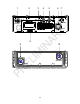
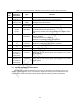
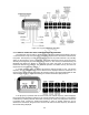
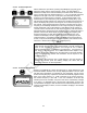
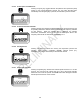
Table Of Contents

2-3
Table 2-1. Front Panel Controls, Indicators and Connector and Rear Panel Connectors
Find
No.
Controls,
Indicators,
Connectors
Type Function
1 Antenna
connector, J3
BNC Connects VHF/UHF Antenna, threaded sleeve is provided to
securely fasten flexible antenna to the transceiver.
2 Liquid Crystal
Display (LCD)
7-segment
display
Alpha-numeric display that shows operating modes, frequency,
messages and measurements.
3 Keypad 12-push-
button keypad
Used to select all operating modes and frequencies.
4 VOL/OFF
a) OFF
b) VOL
Rotary control
with switch
Full CCW position turns transceiver off.
Continuously variable control adjusts handset and speaker audio
level.
5 SQ/OFF Rotary control
with switch
Continuously variable control adjusts squelch threshold in the PT
mode of operation.
Full CCW position turns squelch off.
Squelch is not operational when CT is selected.
6 X-mode
J2
26-pin
connector
Connects transceiver to peripheral devices such as COMSEC
equipment, remote control unit and test equipment.
7 HDST
J4
6-pin audio
connector
Handset connector for H-189/GR or H-250/U handset
8 Speaker
9 Battery
connector J1
(Located on
back-panel)
6-pin battery
connector
Connects transceiver to a power source such as the UBC-100
battery case or UAC-100 AC supply. See Paragraph 1-9 for power
source options.
10 Battery
connector J5
(Located on
back-panel)
6-pin battery
connector
Connects transceiver to a power source such as the UBC-100
battery case or UAC-100 AC supply. See Paragraph 1-9 for power
source options.
2-3. KEYPAD AND DISPLAY FUNCTIONS
The following procedures describe how to set-up the transceiver for operation in any of the
possible operating modes. Figure 2-2 shows the display
and the key-pad and identifies the key
functions. Each will be discussed in further detail as specific operating modes are described.