
User Manual

DRAFT COPY
NOMAD MXU Administration Manual
3:33 PM 02/12/99
DRAFT COPY
23
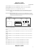
Channel 3 Indicator: Illuminated when NOMAD MXU is making a call over the Constellations.
Channel 4 Indicator: Illuminated when NOMAD MXU is making a call over the Constellations.
Power Indicator: Illuminated whenever the NOMAD MXU is powered on.
On Push Button Switch: Activates NOMAD MXU on. Note: Due to the NOMAD MXU running self
tests, there will be a delay of approximately 60 seconds before the ready indictor is
activated.
Power Down Sequence Push Button Switch: This switch instructs the NOMAD MXU to power down.
NOTE: there will be a delay of approximately 60 seconds form the time the pushbutton is
pushed and the power light goes out. This is caused by the microprocessor processing data
and storing the results on the internal hard drive.
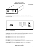
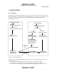
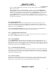
2.3.2 Back Panel
Figure 2.3.2-1: Nomad Back Panel
The connections and access panel on the on the back panel are illustrated in Figure 2.3.2-1 and defined as
follows:
Antenna 1 Connector: Connects the NOMAD MXU’s internal LBT to the antenna located outside the
building.
Antenna 2 Connector: Connects the NOMAD MXU’s internal LBT to the antenna located outside the
building.
Antenna 3 Connector: Connects the NOMAD MXU’s internal LBT to the antenna located outside the
building.
Antenna 4 Connector: Connects the NOMAD MXU’s internal LBT to the antenna located outside the
building.
Line 1 Connector: RJ11 connector for connecting the NOMAD MXU to the Local PSTN
Line 2 Connector: RJ11 connector for connecting the NOMAD MXU to the Local PSTN
Line 3 Connector: RJ11 connector for connecting the NOMAD MXU to the Local PSTN
Line 4 Connector: RJ11 connector for connecting the NOMAD MXU to the Local PSTN
Fan
Power
Supply
Fan
SIM Access Cover
Antenna 1
Antenna 2
Antenna 3
Antenna 4
110-230VAC
50/60 HZ
Line 1 Line 2
Line 3 Line 4
Dat/Fax
#1
Dat/Fax
#4
Dat/Fax
#3
Dat/Fax
#2