
User Manual

DRAFT COPY
NOMAD MXU Administration Manual
3:33 PM 02/12/99
DRAFT COPY
22
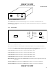
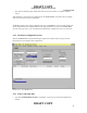
Figure 3.2-1: NOMAD Console
The NOMAD MXU Console is illustrated in Figure 3.2-1. The console is a standard 19 inch rack
mountable drawer. The displays on the front panel, and the connections on the rear panel, are described in
the following paragraphs.
2.3.1 Front Panel
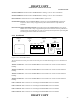
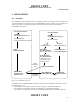
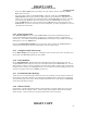
Figure 3.2.1-1: NOMAD Front Panel
The controls and indicators on the front panel are illustrated in Figure 3.2.1-1 and defined as follows:
Control Interface: RS232 interface that allows the operation of the NOMAD MXU to be administered or
monitored via the Personal Computer (PC) defined in paragraph 4.1.3.1
Line 1 Indicator: Illuminated when Line 1, attached to the PSTN is active.
Line 2 Indicator: Illuminated when Line 2, attached to the PSTN, is active.
Line 3 Indicator: Illuminated when Line 3, attached to the PSTN, is active.
Line 4 Indicator: Illuminated when Line 4, attached to the PSTN, is active.
Ready Indicator: Illuminated when the NOMAD MXU has passed the power on diagnostics and is ready
to pass data.
Channel 1 Indicator: Illuminated when NOMAD MXU is making a call over the Constellations.
Channel 2 Indicator: Illuminated when NOMAD MXU is making a call over the Constellations.
Line 1
Line 2
Line 3
Line 4
Channel 1
Channel 2
Channel 3
On
Ready
Power
Channel 1
Initiate
Power
Down
Sequence
Control Interface
Line 1
Line 2
Line 3
Line 4
Channel 1
Channel 2
Channel 3
On
Ready
Power
Channel 1
Power
Down
Sequence
Control Interface