
Installation Manual

DRAFT COPY
NOMAD MXU Installation Manual
3:36 PM 02/12/99
DRAFT COPY
11
4 Installation
4.1 Console Installation
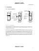
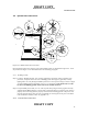
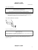
Figure 4.1-1: Console Mounting
The NOMAD MXU is designed to be mounted in a standard 19 inch rack as illustrated in left
front view of figure 4.1-1. Slides, shelves or supports to mount the MXU in a rack are not
included in the MXU package.
Interconnection of the antenna to the NOMAD MXU is covered in section 4.3.2; however,
the location of the MXU console is directly related to the length of the cables supplied with
the NOMAD MXU. If the back of the NOMAD MXU is mounted less than 1.5 meters from
the surge protectors (Line Item 26), the standard W3 cables (line item 25) supplied with the
MXU will work as illustrated in the center view of Figure 4.1-1. If the back of the NOMAD
MXU is mounted more than 1.5 meters of the surge protectors, the user will have to procure
custom cables as defined in Appendix “B” of this document and illustrated in the right view
in Figure 4.1-1.
Line 1
Line 2
Line 3
Line 4
Channel 1
Channel 2
Channel 3
On
Ready
Power
Channel 1
Initiate
Power
Down
Sequence
Contr ol In ter fac e
Front View
19 inch Rack
Back View
19 inch Rack
Less than 1.5 meters
from the Surge
Suppressors
Back View
19 inch Rack
More than 1.5 meters
from the Surge
Suppressor
Low Loss Coax
from the Surge
Suppressors
Low Loss Coax
Constraint
(Users Supplied)
Line Item 25,
Four W3 Cable
Assemblies.
Required for
MXU connector
strain relief.
Line Item 25,
Four W3 Cable
Assemblies.
Line Item 26, Four
Surge Protectors
Miunted on the Wall
Strain Reliefs
(User Provided)
Required to
protect the MXU
Antenna COnnectors