
Installation Manual

DRAFT COPY
NOMAD MXU Installation Manual
3:36 PM 02/12/99
DRAFT COPY
9
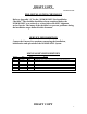
3 Description of Material Received
3.1 User Site, Material Received
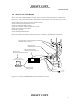
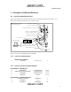
This section contains lists of material received at the user and gateway installation sites, Figure 3.1-1
illustrates the assembly and location of the various line items.
Figure 3.1-1: User Site, NOMAD Equipment Assembly
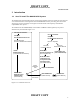
3.1.1 Console and Mounting Kit
NOMAD MXU CONSOLE
1 Console ??????????? 1
3.1.2 Antenna Assembly and Mounting Kit
01-P43455F001 ANTENNA KIT
2 CROSSBAR 07-P43411F001 1 or 2
3 CABLE MOUNTING BRACKET 07-P43412F001 2 or 4
4 ANTENNA 85-P43415F001 2 or 4
5 ENDCAP FCR-16 2 or 4
01-P43460F001 ANTENNA MAST KIT
6 UNIVERSAL TRIPOD RONNIE 5 1
7 TARPADS 78 1
8 LAG BOLTS 91478A546 14
Line 1
Line 2
Line 3
Line 4
Channel 1
Channel 2
Channel 3
On
Ready
Power
Chann el 1
Initiat e
Power
Down
Sequence
Cont rol Inte rface
110-230VAC
50/60 HZ
Line Item 4, Antenna (2 or 4)
Auxiliary Control PC
(Optional, Customer Furnished)
RS232, Null Modem Cable (Customer Furnished)
Power Cord
Line Item 26, Surge Suppressors (2 or 4)
Line Item 1, NOMAD Console
Line Item 11, Lighting Rod
Line Item 23, Ouside Coax (2 or 4)
Line Item 24, Inside Coax (2 or4)
Line Item 25, Antenna Lead In Coax (2 or 4)
Line Item 27, Telephone Cables (4)
Line Item 28, Power Cord
Line Items 6 - 21, Antenna Mast Kit
NOTE:
Line Item numbers refer to
the parts lists in section 3.0