
User's Manual
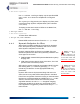
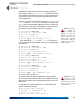
Table Of Contents
- Chapter 1 Introduction
- Chapter 2 Mesh Point CLI and Administrative Access
- Chapter 3 Networking and Radio Configuration
- 3.1 Network Interfaces
- 3.2 Network Bridging
- 3.2.1 Bridging Configuration
- 3.2.2 FastPath Mesh Bridging
- 3.2.3 Fine-tuning FastPath Mesh Network Performance
- 3.2.3.1 Selecting the FastPath Mesh Multicast Transmit Mode
- 3.2.3.2 Setting the FastPath Mesh Packet Interval
- 3.2.3.3 Setting the FastPath Mesh Transmit Control Level
- 3.2.3.4 Setting Multicast Video Clamping Thresholds
- 3.2.3.5 Setting Mesh Routing Reactivity
- 3.2.3.6 Setting Mesh Packet Time To Live
- 3.2.3.7 Viewing Current Mesh Performance Parameters
- 3.2.3.8 Frame Processor Parameters
- 3.2.4 STP Bridging
- 3.3 Global Radio Settings
- 3.4 Individual Radio Settings
- 3.4.1 Radio Band, Short Preamble, Guard Interval
- 3.4.2 Channel Selection
- 3.4.3 Distance, Beacon Interval, Noise Immunity
- 3.4.4 Network Type, Antenna Gain, Tx Power
- 3.4.5 MIMO
- 3.4.6 STBC
- 3.4.7 Channel Lock and Other Channel Selection Features
- 3.4.8 DFS, TDWR, and Channel Exclusion
- 3.4.9 Radio BSS Settings
- 3.4.9.1 BSS Radio, BSS Name and SSID
- 3.4.9.2 WDS Bridging or AP Infrastructure Configuration
- 3.4.9.3 BSS State, SSID Advertising and Drop Probe Requests
- 3.4.9.4 BSS STA Idle Timeout and 802.11g-Only Settings
- 3.4.9.5 BSS Unicast Transmission Rate Settings
- 3.4.9.6 BSS WMM QoS Setting
- 3.4.9.7 BSS Fragmentation and RTS Thresholds
- 3.4.9.8 BSS DTIM Beacon Countdown
- 3.4.9.9 BSS VLANs Settings
- 3.4.9.10 BSS Fortress Security Zone
- 3.4.9.11 FastPath Mesh BSS Cost Offset
- 3.4.9.12 BSS Multicast Settings
- 3.4.9.13 Bridging MTU and Beacon Encryption
- 3.4.9.14 BSS Description
- 3.4.9.15 BSS Wi-Fi Security Configuration
- 3.4.10 Antenna Tracking / Rate Monitoring
- 3.4.11 ES210 Mesh Point STA Settings and Operation
- 3.4.11.1 STA Radio, Name, SSID and SSID Roaming
- 3.4.11.2 STA State
- 3.4.11.3 STA Unicast Transmission Rate Settings
- 3.4.11.4 STA Background Scanning
- 3.4.11.5 STA WMM QoS Setting
- 3.4.11.6 STA Fragmentation and RTS Thresholds
- 3.4.11.7 STA Multicast Rate
- 3.4.11.8 STA Description
- 3.4.11.9 STA Wi-Fi Security Configuration
- 3.4.11.10 Editing or Deleting a STA Interface Connection
- 3.4.11.11 Establishing a STA Interface Connection
- 3.4.11.12 ES210 Station Access Control Lists
- 3.5 Local Area Network Configuration
- 3.6 Time and Location Configuration
- 3.7 GPS and Location Configuration
- 3.8 DHCP and DNS Services
- 3.9 Ethernet Interfaces
- 3.10 Quality of Service
- 3.11 VLANs Implementation
- 3.12 ES210 Mesh Point Serial Port Settings
- 3.13 Mesh Viewer Protocol Settings
- Chapter 4 Network Security, Authentication and Auditing
- 4.1 Fortress Security Settings
- 4.1.1 Operating Mode
- 4.1.2 FIPS Settings
- 4.1.3 MSP Encryption Algorithm
- 4.1.4 Encrypted Data Compression
- 4.1.5 MSP Key Establishment
- 4.1.6 MSP Re-Key Interval
- 4.1.7 Key Beacon Interval
- 4.1.8 Fortress Legacy Devices
- 4.1.9 Encrypted Zone Cleartext Traffic
- 4.1.10 Encrypted Zone Management Settings
- 4.1.11 Authorized Wireless Client Management Settings
- 4.1.12 Turning Mesh Point GUI Access Off and On
- 4.1.13 SSH Access to the Mesh Point CLI
- 4.1.14 Blackout Mode
- 4.1.15 Allow Cached Credentials
- 4.1.16 Fortress Access ID
- 4.2 Digital Certificates
- 4.3 Access Control Entries
- 4.4 Internet Protocol Security
- 4.5 Authentication and Timeouts
- 4.5.1 Authentication Servers
- 4.5.2 Internal Authentication Server
- 4.5.2.1 Basic Internal Authentication Server Settings
- 4.5.2.2 Certificate Authority Settings
- 4.5.2.3 Global User and Device Authentication Settings
- 4.5.2.4 Local 802.1X Authentication Settings
- 4.5.2.5 OCSP Authentication Server Settings
- 4.5.2.6 OCSP Cache Settings and Management
- 4.5.2.7 Internal Authentication Server Access Control Lists
- 4.5.3 User Authentication
- 4.5.4 Client Device Authentication
- 4.5.5 Session Idle Timeouts
- 4.6 ACLs and Cleartext Devices
- 4.7 Remote Audit Logging
- 4.8 Wireless Schedules
- 4.1 Fortress Security Settings
- Chapter 5 System Options, Maintenance and Licensing
- Chapter 6 System and Network Monitoring
- Index
- Glossary

Fortress ES-Series CLI Guide: Network Security, Authentication and Auditing
132
4.4.2 Interface Security Policy Database Entries
CAUTION:
When
L2TP is enabled
(Section 4.4.6), do not
apply an SPD entry to a
wireless bridging
enabled BSS
(
Ena-
bleWds[Y]
)
.
L2TP/IPsec
is not supported for
bridging BSSs.
When IPsec is globally enabled and configured (refer to
Section 4.4.1), the Mesh Point configuration can include up to
100 SPD entries, each associated with one of the Mesh Point’s
network interfaces.
An interface with at least one SPD configured for it is enabled
to process IPsec traffic. An interface with no SPD configured
for it is disabled for IPsec traffic.
Each SPD entry defines the traffic to which it will apply by a
specified local subnet of IP addresses—the source of outbound
traffic and destination of inbound traffic. You can likewise
specify a remote subnet of IP addresses to which an SPD will
apply—defining traffic by its outbound destination/inbound
source—as well as the IP address of the connecting device.
How traffic defined by an SPD entry will be handled is
determined by the specified
Action, as shown in Table 4.1.
Traffic on an interface that has no matching SPD definition will
be handled according to whether any SPD entry has been
configured for that interface:
NOTE: Devices
that implement
the IPsec model are
sometimes referred to as
red/black boxes.
An interface with no SPD entry configured for it permits
packets to pass unprotected by IPsec. Such an interface is a
red interface, in IPsec terms, indicating the unprotected
status of traffic on that interface.
An interface with at least one SPD entry configured for it
drops any packet that does not match (one of) the traffic
selector(s) defined by the SPD entry(-ies) configured for that
interface. In IPsec terms, such an interface is functioning as
a black interface, indicating the secure status of any traffic
passing on it.
NOTE: Creating or
deleting an SPD
entry causes all active
IPsec SAs to be renego-
tiated.
Add an SPD entry with add spd:
# add spd
Name (policy name): From172NetTo520
Interface (Interface name): enc
Local address (Local address): 172.0.0.0
Local mask (Local mask): 255.0.0.0
Remote address (Remote address): 172.28.128.202
Remote mask (Remote mask): 255.255.255.255
Peer address (IPsec peer address): 172.28.120.121
Table 4.1 Configurable SPD Entry Actions
action inbound packets outbound packets
Apply
must be IPsec-protected IPsec-encrypt and send as ESP
Bypass
must not be IPsec-protected send unprotected by IPsec
Drop
drop without further processing