
User's Manual
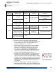
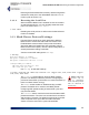
Table Of Contents
- Chapter 1 Introduction
- Chapter 2 Mesh Point CLI and Administrative Access
- Chapter 3 Networking and Radio Configuration
- 3.1 Network Interfaces
- 3.2 Network Bridging
- 3.2.1 Bridging Configuration
- 3.2.2 FastPath Mesh Bridging
- 3.2.3 Fine-tuning FastPath Mesh Network Performance
- 3.2.3.1 Selecting the FastPath Mesh Multicast Transmit Mode
- 3.2.3.2 Setting the FastPath Mesh Packet Interval
- 3.2.3.3 Setting the FastPath Mesh Transmit Control Level
- 3.2.3.4 Setting Multicast Video Clamping Thresholds
- 3.2.3.5 Setting Mesh Routing Reactivity
- 3.2.3.6 Setting Mesh Packet Time To Live
- 3.2.3.7 Viewing Current Mesh Performance Parameters
- 3.2.3.8 Frame Processor Parameters
- 3.2.4 STP Bridging
- 3.3 Global Radio Settings
- 3.4 Individual Radio Settings
- 3.4.1 Radio Band, Short Preamble, Guard Interval
- 3.4.2 Channel Selection
- 3.4.3 Distance, Beacon Interval, Noise Immunity
- 3.4.4 Network Type, Antenna Gain, Tx Power
- 3.4.5 MIMO
- 3.4.6 STBC
- 3.4.7 Channel Lock and Other Channel Selection Features
- 3.4.8 DFS, TDWR, and Channel Exclusion
- 3.4.9 Radio BSS Settings
- 3.4.9.1 BSS Radio, BSS Name and SSID
- 3.4.9.2 WDS Bridging or AP Infrastructure Configuration
- 3.4.9.3 BSS State, SSID Advertising and Drop Probe Requests
- 3.4.9.4 BSS STA Idle Timeout and 802.11g-Only Settings
- 3.4.9.5 BSS Unicast Transmission Rate Settings
- 3.4.9.6 BSS WMM QoS Setting
- 3.4.9.7 BSS Fragmentation and RTS Thresholds
- 3.4.9.8 BSS DTIM Beacon Countdown
- 3.4.9.9 BSS VLANs Settings
- 3.4.9.10 BSS Fortress Security Zone
- 3.4.9.11 FastPath Mesh BSS Cost Offset
- 3.4.9.12 BSS Multicast Settings
- 3.4.9.13 Bridging MTU and Beacon Encryption
- 3.4.9.14 BSS Description
- 3.4.9.15 BSS Wi-Fi Security Configuration
- 3.4.10 Antenna Tracking / Rate Monitoring
- 3.4.11 ES210 Mesh Point STA Settings and Operation
- 3.4.11.1 STA Radio, Name, SSID and SSID Roaming
- 3.4.11.2 STA State
- 3.4.11.3 STA Unicast Transmission Rate Settings
- 3.4.11.4 STA Background Scanning
- 3.4.11.5 STA WMM QoS Setting
- 3.4.11.6 STA Fragmentation and RTS Thresholds
- 3.4.11.7 STA Multicast Rate
- 3.4.11.8 STA Description
- 3.4.11.9 STA Wi-Fi Security Configuration
- 3.4.11.10 Editing or Deleting a STA Interface Connection
- 3.4.11.11 Establishing a STA Interface Connection
- 3.4.11.12 ES210 Station Access Control Lists
- 3.5 Local Area Network Configuration
- 3.6 Time and Location Configuration
- 3.7 GPS and Location Configuration
- 3.8 DHCP and DNS Services
- 3.9 Ethernet Interfaces
- 3.10 Quality of Service
- 3.11 VLANs Implementation
- 3.12 ES210 Mesh Point Serial Port Settings
- 3.13 Mesh Viewer Protocol Settings
- Chapter 4 Network Security, Authentication and Auditing
- 4.1 Fortress Security Settings
- 4.1.1 Operating Mode
- 4.1.2 FIPS Settings
- 4.1.3 MSP Encryption Algorithm
- 4.1.4 Encrypted Data Compression
- 4.1.5 MSP Key Establishment
- 4.1.6 MSP Re-Key Interval
- 4.1.7 Key Beacon Interval
- 4.1.8 Fortress Legacy Devices
- 4.1.9 Encrypted Zone Cleartext Traffic
- 4.1.10 Encrypted Zone Management Settings
- 4.1.11 Authorized Wireless Client Management Settings
- 4.1.12 Turning Mesh Point GUI Access Off and On
- 4.1.13 SSH Access to the Mesh Point CLI
- 4.1.14 Blackout Mode
- 4.1.15 Allow Cached Credentials
- 4.1.16 Fortress Access ID
- 4.2 Digital Certificates
- 4.3 Access Control Entries
- 4.4 Internet Protocol Security
- 4.5 Authentication and Timeouts
- 4.5.1 Authentication Servers
- 4.5.2 Internal Authentication Server
- 4.5.2.1 Basic Internal Authentication Server Settings
- 4.5.2.2 Certificate Authority Settings
- 4.5.2.3 Global User and Device Authentication Settings
- 4.5.2.4 Local 802.1X Authentication Settings
- 4.5.2.5 OCSP Authentication Server Settings
- 4.5.2.6 OCSP Cache Settings and Management
- 4.5.2.7 Internal Authentication Server Access Control Lists
- 4.5.3 User Authentication
- 4.5.4 Client Device Authentication
- 4.5.5 Session Idle Timeouts
- 4.6 ACLs and Cleartext Devices
- 4.7 Remote Audit Logging
- 4.8 Wireless Schedules
- 4.1 Fortress Security Settings
- Chapter 5 System Options, Maintenance and Licensing
- Chapter 6 System and Network Monitoring
- Index
- Glossary

Fortress ES-Series CLI Guide: Networking and Radio Configuration
99
the VLAN used for multicast traffic by subscribed FPMPs
(described in Section 3.2.2).
5 Enable VLANs on the Mesh Point.
When FastPath Mesh is used for bridging, the Mesh Point can
support up to eight VLANs, in
Enabled VLAN Mode. When
BridgingMode is
Off
, the Mesh Point can support up to 48
VLANs, in
Enabled VLAN Mode.
NOTE: Layer 2 dis-
covery protocols
must also be turned off
on any 3rd-party net-
work AP. Bridging loop
detection is incompati-
ble with VLAN transla-
tion, which is intended
to support an intention-
al loop in the L2 switch.
3.11.0.0.2 Translate VLAN Mode
You can set VLAN Mode to Translate only when the Mesh
Point’s global bridging
Mode is Off. Translate VLAN Mode is
incompatible with FastPath
Mesh (the default) and STP bridging
link management.
In
Translate VLAN Mode, pairs of encrypted-side and clear-
side VLAN IDs are used to map packets with matching VLAN
ID tags between encrypted and clear VLANs on the Mesh
Point. Each such VLAN pair therefore constitutes a
VLAN Map.
When a packet tagged with a VLAN ID that matches the
Encrypted Side VLAN ID of a VLAN Map is received on any
encrypted interface, the Mesh Point re-tags the packet with the
VLAN Map’s Clear Side VLAN ID as it passes the packet to any
clear interface. Likewise, when a packet is received on any
clear interface with a VLAN ID tag that matches the
Clear Side
VLAN ID of a configured VLAN Map, the packet is re-tagged
with the
Encrypted Side VLAN ID as it is passed to any
encrypted interface.
NOTE:
Any num-
ber of VLAN
trunks can be config-
ured on a Mesh Point in
Translate
VLAN
Mode
.
In this way VLAN ID-tagged packets can be passed in either
direction between VLANs on the Mesh Point’s clear and
encrypted interfaces as their VLAN ID tags are translated
accordingly. VLAN user-priority tags are preserved during
VLAN translation.
You can also configure a VLAN map (
vlanmap
), in which the
same VLAN ID is configured as the
Encrypted Side VLAN ID
and the
Clear Side VLAN ID, causing packets with matching
VLAN ID tags to pass between the Mesh Point’s encrypted and
clear interfaces without VLAN translation.
NOTE:
There is no
need for
VLAN
Map
s to be associated
with specific interfaces.
When the Mesh Point is in Translate VLAN Mode, an
incoming packet will be dropped, rather than forwarded from
clear to encrypted or encrypted to clear, if there is no VLAN
map with a matching VLAN ID configured for it.
VLAN IDs
1 through 4094 (inclusive) can be used in VLAN
maps. Note, however, that VLAN ID 1 is the default
Management VLAN ID. The VLAN IDs you configure in
translation maps must be present in the Mesh Point’s
Active
VLAN ID Table
(described in Section 3.11.1, below).
VLAN translation maps may not overlap: a given VLAN ID can
be used in only one VLAN map in the Mesh Point’s
vlanmap