
User's Manual
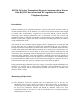
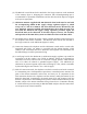
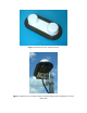
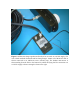
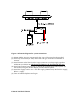

Figure 4. Schematic diagram for system connections
(1) Mount AD510-10 active antenna with clear view of sky using bracket supplied.
(2) Attach top end of 40m (or 30m) down-lead to N type connector on underside of
antenna.
(3) Attach bottom end of down-lead to N type connector on voltage supply regulator
AD510-40 (or AD510-30). The down-lead must not be shortened by the user.
(4) Attach interconnect between TNC on AD510-40 (or AD510-30) and telephone (or
base station) using the antenna adapter provided with the phone.
(5) Attach DC supply lead to +9 to +36V DC supply (500mA max). Red lead to +supply,
Blue to –supply.
(6) Turn on Iridium telephone and log-in.
END OF INSTRUCTIONS