
User's Manual
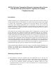
(2) The RG213U coaxial down-lead is attached to the N-type connector on the underside
of the antenna, figure 2. Wrapping the connectors with self-amalgamating tape is
recommended for permanent installations and the cable should be taped or strapped
to the spar as appropriate.
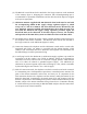
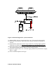
(3) AD510-10 antennae supplied with 40m RG213U down-leads must be used with
the accompanying AD510-40 DC supply voltage regulators (figure 3), which
accept +9V to +36V dc at 500mA. The down-lead must not be shortened by the
user. Similarly, antennae supplied with 30m RG213U down-leads are only to be
used with the AD510-30 DC supply voltage regulators provided. Again, the
down-lead must not be shortened. In all other respects, however, the assembly
and operation of the 30m cable systems are identical to those with 40m cables.
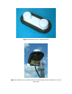
(4) The AD510-40 (or AD510-30) supply voltage regulator should be positioned close to
the telephone base-station or handset. The RG213U down-lead is then attached to
the N type connector on the AD510-40 (figures 3 and 4).
(5) Connection between the telephone and the AD510-40 is made with a coaxial cable
terminated with TNCs. An adapter is provided with the Iridium handset, which
enables a TNC terminated cable to be attached to the telephone. The AD510-40 case
has drilled flanges to enable permanent fixing.
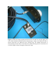
(6) A 3m flying lead for the AD510-40 (or AD510-30) supply regulator is provided for
connection to the DC supply (+9 to 36Vdc at 500mA), which can be trimmed (or
extended) if necessary. The red wire is connected to supply positive, whilst the blue
wire is for either an isolated or grounded negative supply. The AD510-40 (or
AD510-30) is protected against output short-circuiting by a fuse, which is resettable
by disconnecting the unit from the +9 to +36Vdc supply.
(7) With all connections made, the telephone can then be turned on and used as normal-
it is transmitting into a load impedance equivalent to a matched passive antenna. The
gains of the antenna transmitter and receiver are factory set to compensate for the
total attenuation between the telephone and the antenna, mainly determined by the
RG213U down-lead. Consequently, the signal output level and frequency from the
antenna is equivalent to that radiating from a passive antenna mounted directly on the
handset, subject to the antenna transmitter being a linear device. Transmitter linearity
is verified with test protocols using an HP 8591 EMC analyser that also ensure there
are no spurious out of band emissions.