
User's Manual
AD510-10 Active Transmitter/Receiver Antenna with a 30m or
40m RG213U down-lead and DC regulator for Iridium
Telephone Systems
Introduction
Iridium telephones were originally designed to operate with passive antennae, either an
element attached directly to the handset, or a remote aerial connected with a short length
of coaxial cable. Unfortunately, a signal loss of more than 3dB in a remote antenna’s
connecting cable degrades performance due to attenuation of both the received and
transmitted signals. A 3dB loss corresponds to approximately 10m of RG213U or 3m of
RG58U coaxial cable, lengths that clearly restrict the mounting options for the antenna
using standard down-leads.
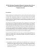
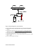
The AD510-10 active Iridium antenna (figures 1&2) is designed for use with 30m (98
feet) or 40m (131 feet) of RG213U coaxial cable terminated with type ‘N’ connectors.
Designed for harsh environments, the AD510-10 consists of two RHCP dipole antennae
housed within 4mm thick GRP radomes mounted on a common base. One antenna is for
signal transmission and one for reception. A linear power amplifier within the base and
connected to the transmitting antenna compensates for signal loss incurred mainly by the
connecting cable. Similarly, a low noise amplifier is attached to the receiving antenna via
a low loss interdigital filter to boost the signal sent to the telephone. The interdigital filter
has a bandwidth of 12 MHz centred on the Iridium band designed to attenuate any out of
band interference that may arise, for example from nearby Inmarsat uplinks.
Using manufacturing techniques proven for a range of extremely rugged GPS/DGP active
antennae, the antenna base is milled from aluminium and hard anodised, giving an
attractive green finish, which is mechanically resilient and resistant to corrosion. The
antenna’s mass is 2.6kg.
Mounting and Operation
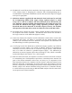
(1) The AD510-10 should be mounted with an unobstructed view of the sky. An
aluminium bracket with V-bolts is provided to attach the antenna to horizontal or
vertical spars up to 60mm in diameter, figure 2. The bracket is shipped inverted on
the end of the AD510-10 antenna and should be detached, turned over, then
repositioned either to the centre or end of the antenna case as required using the
mounting holes in the base.