
Integration Guide

OEM LTE PCIe Mini Module Integration
August 2012 General Dynamics Broadband Proprietary and Confidential Page 6 of 9
Subject to Non Disclosure Agreement
3 Module Connections
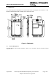
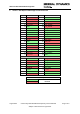
3.1 PCI Express Mini Interface (J1)
The General Dynamics Broadband PCI Express Mini module is provided with a 52 pin edge
connector for connection to the external application. This connection supports the following interface
types and these are described below. The pinout is shown in Annex 1.
3.1.1 Universal Serial Bus
The PCI Express edge connector provides a USB 2.0 interface, this interface supports low speed
(1.5Mbps), full speed (12Mbps) and High speed (480Mbps) operation.
3.1.2 SIM Interface
The PCI Express edge connector provides a 4 line SIM interface to allow use with Subscriber Identity
Modules if required, this interface supports both 1.8V and 3.0V SIM’s. The SIM interface does not
provide ESD protection and this should be provided by the host device.
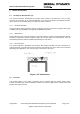
3.1.3 RF Connections
The General Dynamics Broadband PCI Express Mini module provides two RF connections for
external antennas. The main port must be connected, the diversity port may or may not be connected
depending upon application. The connector type is the Hirose U.FL series.
Figure 1: RF Connections
3.2 DC Power
The module requires a DC supply of between 3.0V to 3.6VDC with the nominal voltage being
3.3VDC, maximum input current is 950mA at 3.3VDC. DC power is applied to the module via the PCI
Express Mini edge connector.