
Integration Guide


OEM TD-CDMA PCI Express Module Integration
May 2013 General Dynamics Broadband Proprietary and Confidential Page 8 of 20
Subject to Non Disclosure Agreement
3.4 Management of Radio Receiver Self-Interference
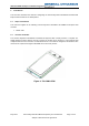
The General Dynamics Broadband TD-CDMA PEM is supplied as a stand-alone PCI Express Card, or
can be mounted on an General Dynamics Broadband TD-CDMA Adaptor card. It is the customer who
then has to integrate the PEM - either on a Host Circuit Board, or mounted within their own Host
Equipment, at which point, the location of the antennas which connect to the PEM are outside of
General Dynamics Broadband control.
Any radio receiver is susceptible to in-band RF interference in its receive band and it is of paramount
importance that the PEM Host Equipment Integration Design team are aware of and take
countermeasures to prevent all Host Equipment, in-band RF interference from reaching the PEM’s
Antennas.
The PEM as a unit is fully shielded by design, external RF Interference from the Host Equipment is
extremely unlikely to get into the TD-CDMA Radio receiver on the PCB and will be coupled to the
receiver by other means. Any Interference from the Host Equipment in the TD-CDMA receive band(s)
will degrade the TD-CDMA receiver performance if present at the antennas. Any such receiver
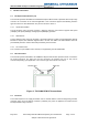
interference is a called an RF “Blocking signal”. The closer the TD-CDMA PEM’s antenna system is
relative to the source of any blocking signals, the worse will be the degradation in Rx Sensitivity
suffered by the TD-CDMA PEM and subsequent customer-perceived Host Equipment performance.
Due to the extremely high performance of the TD-CDMA PEM RF Receivers, tiny levels of in-band
interference may cause major loss of performance. To put this in perspective, the Class B EMC limit is
approximately 70dB higher than the smallest signal that the TD-CDMA Receiver can receive (receiver
sensitivity is approximately -123dBm (-16dBµV).
Therefore host equipment which is compliant with relevant EMC emission regulations is likely to cause
interference and performance degradation to the TD-CDMA PEM receivers.
However, all of the EMC design countermeasures must be applied when designing the Host
Equipment, to prevent RF Blocking signals – they are the first line of suppression and are good design
practice. Each engineering discipline: Digital, Power, RF, Mechanical and Thermal must be involved
from the outset, to provide the suppression performance required.
3.4.1 PCB Level
Any PCB with high-clock rate digital signals, imperfect supply rails and any signals with fast edges
must be carefully designed during layout to produce a low emission profile PCB.
By listing the speeds of all clocks, processors and busses, then computing their harmonics up to
2690MHz, it is simple to see which parts of the circuitry are most likely to generate RF Blocking
signals. Believing that any of those harmonics will destroy RF Receiver performance if they are not
suppressed by design and then being meticulous attention during layout are the key to suppressing
them at source.
a. Top and bottom surfaces should be flood-filled with a copper ground plane and tracking on the
outer layers should be avoided.
b. The perimeter of the PCB should have ground copper on each layer and all layers should be
stitched with ground vias.
c. There must be no slots in the surface ground planes or apertures above fast-moving signals
on inner layers – particularly digital buses.
d. Care should be taken to provide ground current return paths for all power circuitry, for the
digital ICs and particularly the clock ICs.
e. Provision should be made for shielding all components on the PCB.