
Integration Guide


OEM TD-CDMA PCI Express Module Integration
May 2013 General Dynamics Broadband Proprietary and Confidential Page 3 of 20
Subject to Non Disclosure Agreement
4.1.7 PEM in Laptop ............................................................................................................... 17
5 Regulatory Information – Model AAU 2.5GHz Band. ......................................... 18
5.1 FCC Requirements for North America .................................................................................. 18
5.1.1 Compliance with FCC Rules and Regulations .............................................................. 18
5.1.2 FCC Labelling Requirements ........................................................................................ 18
5.1.3 Exposure to Radio Frequency Signals .......................................................................... 18
5.1.4 Antenna Gains for Standalone Operation ..................................................................... 19
6 Annex 1: PCI Express Mini Edge Connector Pinout .......................................... 20
Figures
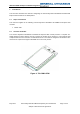
Figure 1: TD-CDMA PEM ........................................................................................................................ 6
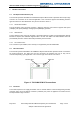
Figure 2: TD-CDMA PEM RF Connections ............................................................................................. 7
Figure 3: TD-CDMA PEM Module - detail ............................................................................................. 11
Figure 4: PEM Unit Assembly - Top ...................................................................................................... 12
Figure 5: PEM Unit Assembly Bottom ................................................................................................... 13
Figure 6: PEM and Adapter Assembly - Top ......................................................................................... 14
Figure 7: PEM and Adaptor Assembly - Bottom.................................................................................... 14
Figure 8: PEM and Adapter Thermal Assembly Structure Section ....................................................... 16