
Integration Guide


OEM TD-CDMA PCI Express Module Integration
May 2013 General Dynamics Broadband Proprietary and Confidential Page 10 of 20
Subject to Non Disclosure Agreement
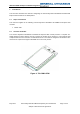
b. If possible, specify a metal enclosure for the Host Equipment if the PEM’s antennas have to
be, or might be mounted in close proximity.
c. Provide an RF connection point on the Host Equipment to which the customer can connect an
alternative remote antenna and make the remote antenna available as an approved
accessory.
d. Provide an extension cable with the Host Equipment which will allow the customer to move it
away from interfering equipment and make the extension cable available as an accessory E.g.
a USB cable to allow the Host Equipment to be moved away from a PC.
e. Processor clocks often determine core clocking speeds and bus switching speeds, both of
which use significant power. If possible, select a clock rate which has no in-band harmonics,
ensure the clock rate can be varied or change to a processor that provides this flexibility.
3.4.5 Provision for “Production Modifications” of Host Equipment
Caution: This section only applies to the host equipment, changes to the TD-CDMA PEM are
prohibited.
Sometimes it is not possible to guarantee that the PCB or Unit design will generate RF interference, or
not. In these instances, it is preferable – at least on the initial spin of a PCB to provide features to allow
correction of problems without delaying deliveries of 1
st
Pass or prototype Host Equipment.
1. Kapton tape covered by self-adhesive copper foil can effectively prevent unshielded PTH pins,
SMT Test-points, Debug points or core vias from radiating. Design apertures into the solder
resist to expose bare copper to allow insulative Kapton tape to be applied over the radiators,
then conductive adhesive copper tape over the kapton, which can be stuck to the exposed
copper, if required.
2. RF suppressor material can sometimes suppress RF blocking signals effectively enough to
allow a sub-optimal card to perform adequately whilst a solution is engineered on a following
revision of PCB. It is useful to have a sample stock of various materials, along with space in
the design (in the likely places) to apply RF suppressor materials, if needed.
3. Conductive paint can be retrospectively applied to the inside of plastic enclosures to provide a
level of shielding. The level achieved depends on the design of the enclosure, particularly it’s
split line design and the sizes of vents and holes within it. It is good practice to design to allow
inner paint shielding at the outset, if required.
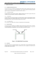
4. A simple and effective way to determine if a product is being desensitised by RF Blocking from
the Host Electronics is to measure receiver performance, then wrap the entire unit up in an
EMC bag (with just the antennas outside), then re-measure and compare the receiver
performance.
5. Be aware that most consumer electronics (especially PCs) are designed to just pass EMC
Class B limits and are huge sources of RF Blockers/interference for 3G and 4G wireless
systems. When the Host Equipment performs as specified, placing it in close proximity to a
PC, Tablet, TV or even a Phone may destroy TD-CDMA receive performance. The end-
customer must be made tactically aware of this.