
User's Manual


P1D Wireless Broadband Modem User Manual
- Page 8 of 46 -
Section 2 – Getting Started
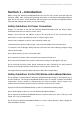
Key Areas on Your Wireless Broadband Modem
Figure 1 below identifies key areas on the P1D Modem. Please review this information before
you begin the installation.
Figure 1 - Key areas on your P1D Wireless Broadband Modem
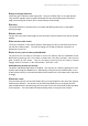
Figure 2 – Top panel on your P1D Wireless Broadband Modem
Power On/Off
Press the power button for one second to turn the modem on. The indicator is lit when the unit
is on and the self-test completed successfully. If the indicator is flashing it means that the
battery is less than 50% charged, this will revert a steady indication once the battery is
charged to greater than 50%.
Connection Status Indicator
The single green LED shows the connection status. The green LED will be illuminated when
you are connected to the data network. When you on present on the network but not
connected, the indicator will flash.
Power Button
Transmit & Receive
Indicator
(2 Amber LEDs)
Connection Status
Indicator
(1 Green LED)
Power On/Off
(1 RED LED)
Power socket
PC interface
cable socket
On/Off switch
Connection and
activity indicators
Rear access panel to
removable battery and
SIM or USIM (option)
Rear connector
for external patch
antenna (option)
(See inset below)
Transmit & Receive
Indicator
Connection Status
Indicator
(1 Green LED)
Power On/Off
(1 RED LED)
On/Off switch
with indicator
Connection status
Signal strength indicators
Traffic activity