
Integration Instructions


P1D Broadband Module Integration
21 March 2001 Proprietary Information Page 8 of 11
3 Module Connections
3.1 Data Interface J2
The IPWireless P1D Broadband module is provided with an 18 pin data connector for connection to
the external application. This connection supports the following interface types and these are
described below.
3.1.1 Universal Serial Bus
The data interface provides a USB 1.1 interface. This is available on pins 1-4 of the data connector.
3.1.2 Ethernet
The data interface provides a 10Mbps Ethernet interface on pins 5-8, power is provided on pin 11 if a
link active LED is required.
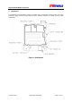
3.2 J2 Connector
3.2.1 Connector Type
The mating connector is a Matushita 18-W AXR30241B101.
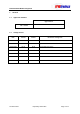
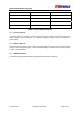
3.2.2 Pin Out
Connector Pin Description Comment
1 USB 5V In
2 USB Ground
3 USB D-
4 USB D+
5 Ethernet RXP
6 Ethernet RXN
7 Ethernet TXP
8 Ethernet TXN
9 Not Used
10 Not Used
11 Ethernet Transformer Power
12 Serial RTS
13 Serial RXD
14 Serial DSR